HP Load Balancing Module High Availability Command Reference Part number: 5998-4227 Software version: Feature 3221 Document version: 6PW100-20130326
Legal and notice information © Copyright 2013 Hewlett-Packard Development Company, L.P. No part of this documentation may be reproduced or transmitted in any form or by any means without prior written consent of Hewlett-Packard Development Company, L.P. The information contained herein is subject to change without notice.
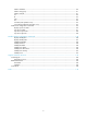
Contents VRRP configuration commands ··································································································································· 1 Common VRRP configuration commands ······················································································································· 1 vrrp mode ·································································································································································· 1 IPv4-base
Track configuration commands ································································································································· 58 display track··························································································································································· 58 track nqa ································································································································································ 59 trac
statistics hold-time ················································································································································ 110 statistics max-group ············································································································································· 111 statistics interval ··················································································································································· 111 tos
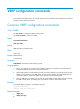
VRRP configuration commands The interfaces that VRRP involves can only be Layer 3 Ethernet interfaces and subinterfaces and VLAN interfaces unless otherwise specified. Common VRRP configuration commands vrrp mode Use vrrp mode to configure the VRRP working mode. Use undo vrrp mode to restore the default. Syntax vrrp mode load-balance undo vrrp mode Default VRRP operates in standard mode. Views System view Default command level 2: System level Parameters load-balance: Specifies the load balancing mode.
IPv4-based VRRP configuration commands display vrrp Use display vrrp to display the state information of VRRP groups. Syntax display vrrp [ verbose ] [ interface interface-type interface-number [ vrid virtual-router-id ] ] [ | { begin | exclude | include } regular-expression ] Views Any view Default command level 1: Monitor level Parameters verbose: Displays detailed state information of VRRP groups.
Table 1 Command output (standard mode) Field Description Current VRRP working mode: Run Mode • Standard—Standard mode. • Load Balance—Load balancing mode. Current VRRP running mode: • Real MAC—Real MAC mode, which means the virtual IP address of the Run Method VRRP group is mapped to the real MAC address of the interface. • Virtual MAC—Virtual MAC mode, which means the virtual IP address of the VRRP group is mapped to the virtual MAC address. Total number of virtual routers Number of VRRP groups.
Table 2 Command output (standard mode) Field Description Current VRRP working mode: Run Mode • Standard—Standard mode. • Load Balance—Load balancing mode. Current VRRP running mode: Run Method • Real MAC—Real MAC mode, which means the virtual IP address of the VRRP group is mapped to the real MAC address of the interface. • Virtual MAC—Virtual MAC mode, which means the virtual IP address of the VRRP group is mapped to the virtual MAC address. Total number of virtual routers Number of VRRP groups.
Field Description Track Interface Interface to be tracked. It is displayed only when the vrrp vrid track interface command is executed. Track Object Track entry to be tracked. It is displayed only when the vrrp vrid track command is executed. State of the tracked interface or track entry. State of a tracked interface: • Up. • Down. • Removed. State State of a track entry: • • • • Invalid. Negative. Positive. Not existing.
Field Description Interface Interface to which the VRRP group belongs. VRID ID of the VRRP group or ID of the virtual forwarder (VF). • If the VRID is number, this field indicates the status of the device in the VRRP group, including Master, Backup, and Initialize. State • If the VRID is VF number, this field indicates the status of the VF in the VRRP group, including Active, Listening, and Initialize.
Owner ID : 0000-5e01-1101 Priority : 255 Active : local Forwarder 02 State : Listening Virtual MAC : 000f-e2ff-0012 (Learnt) Owner ID : 0000-5e01-1103 Priority : 127 Active : 10.1.1.3 Forwarder Weight Track Information: Track Object : 1 State : Positive Weight Reduced : 250 Forwarder Switchover Track Information: Track Object Member IP : 2 State : Positive : 10.1.1.
Field Become Master Description Time to wait before the device becomes the master. The unit is milliseconds. Only devices in backup mode have this information. Authentication type: Auth Type • None—No authentication. • Simple—Simple authentication. • MD5—MD5 authentication. Key Authentication key. Virtual IP Virtual IP address of the VRRP group. List of IP addresses of members in the VRRP group. This address list is displayed only when the VRRP group operates in load balancing mode.
Field Description State of a VF: State • Active. • Listening. • Initialize. Virtual MAC Virtual MAC address of the VF. Owner ID Real MAC address of the interface of the VF owner. Priority VF priority. Active IP address of the interface of the AVF. If the current VF is the AVF, it is displayed as local. Forwarder Weight Track Configuration Weight track configuration of the VF. It is displayed only when the vrrp vrid weight track command is executed. Track Object Weight track entry.
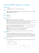
Views Any view Default command level 1: Monitor level Parameters interface interface-type interface-number: Displays VRRP group statistics of the specified interface. The interface-type interface-number argument specifies an interface by its type and number. vrid virtual-router-id: Displays statistics of the specified VRRP group. The virtual-router-id argument specifies a VRRP group by its group number, which ranges from 1 to 255. |: Filters command output by specifying a regular expression.
Invalid Type Pkts Rcvd : 0 Advertisement Interval Errors : 0 IP TTL Errors : 0 Auth Failures : 0 Invalid Auth Type : 0 Auth Type Mismatch : 0 Packet Length Errors : 0 Address List Errors : 0 Become Master : 2 Redirect Timer Expires : 0 Become AVF : 1 Time-out Timer Expires : 0 Adver Rcvd : 0 Request Rcvd : 0 Adver Sent : 1460 Request Sent : 1 Reply Rcvd : 0 Release Rcvd : 0 Reply Sent : 0 Release Sent : 0 Priority Zero Pkts Rcvd : 0 VF Priority Zero Pkts Rcvd : 0 Pr
Field Description Version Errors Total number of packets with version errors. VRID Errors Total number of packets with VRID errors. Table 6 Command output (load balancing mode) Field Description Interface Interface to which the VRRP group belongs. VRID Serial number of the VRRP group. CheckSum Errors Number of packets with checksum errors. Version Errors Number of packets with version errors. Invalid Type Pkts Rcvd Number of packets with incorrect packet type.
Field Description Global statistics Global statistics about all VRRP groups. CheckSum Errors Total number of packets with checksum errors. Version Errors Total number of packets with version errors. VRID Errors Total number of packets with VRID errors. Related commands reset vrrp statistics reset vrrp statistics Use reset vrrp statistics to clear VRRP group statistics.
undo vrrp method Default The virtual MAC addresses are mapped to the virtual IP addresses of the VRRP groups. Views System view Default command level 2: System level Parameters real-mac: Maps the real MAC address of the interface to the virtual IP address of the VRRP group. virtual-mac: Maps the virtual MAC address to the virtual IP address of the VRRP group. Usage guidelines Specify the type of the MAC addresses mapped to the virtual IP address before creating a VRRP group.
therefore the packet TTL value will not be changed. When the master of a VRRP group advertises VRRP packets, it sets the packet TTL to 255. After you configure to check the VRRP packet TTL. When the backups of the VRRP group receive VRRP packets, they check the packet TTL and drop the VRRP packets whose TTL is smaller than 255 to prevent attacks from other network segments.
Before executing the command, create a VRRP group on an interface and configure the virtual IP address of the VRRP group. You might configure different authentication modes and authentication keys for the VRRP groups on an interface. However, the members of the same VRRP group must use the same authentication mode and authentication key. Examples # Set the authentication mode to simple and authentication key to Sysname for VRRP group 1 on interface GigabitEthernet 0/1 to send and receive VRRP packets.
Examples # Enable preemption on the device in VRRP group 1, and set the preemption delay to five seconds. system-view [Sysname] interface gigabitethernet0/1 [Sysname-GigabitEthernet0/1] vrrp vrid 1 virtual-ip 10.1.1.1 [Sysname-GigabitEthernet0/1] vrrp vrid 1 preempt-mode timer delay 5 Related commands display vrrp vrrp vrid priority Use vrrp vrid priority to configure the priority of the device in the specified VRRP group. Use undo vrrp vrid priority to restore the default.
Related commands display vrrp vrrp vrid timer advertise Use vrrp vrid timer advertise to configure the Adver_Timer of the specified VRRP group. Use undo vrrp vrid timer advertise to restore the default. Syntax vrrp vrid virtual-router-id timer advertise adver-interval undo vrrp vrid virtual-router-id timer advertise Default The Adver_Timer is 1 second. Views Interface view Default command level 2: System level Parameters virtual-router-id: VRRP group number, which ranges from 1 to 255.
vrrp vrid track Use vrrp vrid track to associate a VRRP group with a track entry and control master switchover or AVF switchover in the VRRP group in response to changes (such as uplink state changes) detected by the track entry. Use undo vrrp vrid track to remove the association between a VRRP group and a track entry. If no track entry is specified, the association between the VRRP group and any track entry is removed.
The vrrp vrid track command cannot take effect on an IP address owner. If you have configured the command on an IP address owner, the configuration takes effect after the device changes to be a non IP address owner. You can create a track entry with the track command before or after you associate it with a VRRP group. For more information about configuring track entries, see High Availability Configuration Guide.
to access external networks because of the uplink failure. This problem can be solved through tracking a specified uplink interface. After you configure to monitor the uplink interface, when the uplink interface is down or removed, the priority of the master is automatically decreased by a specified value, allowing a higher priority device in the VRRP group to become the master. Before executing the command, create a VRRP group on an interface and configure the virtual IP address of the VRRP group.
Parameters virtual-router-id: VRRP group number, which ranges from 1 to 255. virtual-address: Virtual IP address. Usage guidelines The system removes a VRRP group after you delete all the virtual IP addresses in it. The virtual IP address of a VRRP group cannot be 0.0.0.0, 255.255.255.255, loopback address, non A/B/C address and other illegal IP addresses such as 0.0.0.1.
reduced weight-reduced: Specifies the value by which the weight decreases, in the range of 1 to 255. The default setting is 30. Usage guidelines The command is effective only when VRRP operates in load balancing mode. Before executing the command, create a VRRP group on an interface and configure the virtual IP address of the VRRP group. When the status of the monitored track entry turns from negative to positive or invalid, the corresponding VFs automatically restore their weights.
vrid virtual-router-id: Displays state information of the specified VRRP group. The virtual-router-id argument specifies a VRRP group by its group number, which ranges from 1 to 255. |: Filters command output by specifying a regular expression. For more information about regular expressions, see System Management Configuration Guide. begin: Displays the first line that matches the specified regular expression and all lines that follow.
Field Description Authentication type: Auth Type • None—No authentication. • Simple—Simple authentication. Virtual IP Virtual IPv6 addresses of the VRRP group. # When VRRP operates in standard mode, display detailed information about all VRRP groups on the device.
Field Description Status of the device in the VRRP group: State • Master. • Backup. • Initialize. Config Pri Configured priority of the device, or in other words, the priority value specified by using the vrrp ipv6 vrid priority command. Running Pri Running priority of the device; the current priority of the device. With VRRP tracking configured, when the state of the monitored interface or track entry changes, the priority of the device changes.
Field Description Pri Reduced Priority value that is reduced when the monitored interface is down or removed, or when the status of the monitored track entry turns to negative. It is displayed only when the vrrp ipv6 vrid track interface or vrrp ipv6 vrid track command is executed. Switchover Switchover mode. If the status of the monitored track entry turns to negative, the backup immediately switches to the master.
Field Description • If VRID is number, this field indicates the IP address of the interface of the master. If the current device is the master, it is displayed as local. Active • If VRID is VF number, this field indicates the IP address of the interface of the active virtual forwarder (AVF). If the current VF is the AVF, it is displayed as local. # When VRRP operates in load balancing mode, display detailed information about all VRRP groups on the device.
Table 10 Command output (load balancing mode) Field Description Current VRRP working mode: Run Mode • Standard—Standard mode. • Load Balance—Load balancing mode. Current VRRP running mode: Run Method • Real MAC—Real MAC mode, which means the virtual IP address of the VRRP group is mapped to the real MAC address of the interface. • Virtual MAC—Virtual MAC mode, which means the virtual IP address of the VRRP group is mapped to the virtual MAC address.
Field Description Track Interface Interface to be tracked. It is displayed only when the vrrp ipv6 vrid track interface command is executed. Track Object Track entry to be tracked. It is displayed only when the vrrp ipv6 vrid track command is executed. State of the tracked interface or track entry. State of a tracked interface: State • Up. • Down. • Removed. State of a track entry: • • • • Invalid. Negative. Positive. Not existing.
Field Description State of a track entry: State Weight Reduced Forwarder Switchover Track Information • • • • Invalid. Negative. Positive. Not existing. Weight value that is reduced when the status of the monitored track entry turns to negative. It is displayed only when the vrrp ipv6 vrid weight track command is executed. VF switchover information. The information is displayed only after the vrrp ipv6 vrid track forwarder-switchover command is executed.
exclude: Displays all lines that do not match the specified regular expression. include: Displays all lines that match the specified regular expression. regular-expression: Specifies a regular expression, a case-sensitive string of 1 to 256 characters. Usage guidelines If you specify both an interface and a VRRP group, only the statistics about the specified VRRP group on the interface are displayed. If you only specify an interface, the statistics about all the VRRP groups on the interface are displayed.
Version Errors : 0 VRID Errors : 0 Table 11 Command output (standard mode) Field Description Interface Interface to which the VRRP group belongs. VRID ID of the VRRP group. CheckSum Errors Number of packets with checksum errors. Version Errors Number of packets with version errors. Invalid Type Pkts Rcvd Number of packets with incorrect packet type. Advertisement Interval Errors Number of packets with advertisement interval errors. Hop Limit Errors Number of packets with hop limit errors.
Field Description Invalid Auth Type Number of packets with authentication failures due to invalid authentication types. Auth Type Mismatch Number of packets with authentication failures due to mismatching authentication types. Packet Length Errors Number of packets with VRRP packet length errors. Address List Errors Number of packets with virtual IP address list errors. Become Master Number of times that the device worked as the master.
Default command level 1: Monitor level Parameters interface interface-type interface-number: Clears VRRP group statistics of a specific interface. interface-type interface-number specifies an interface by its type and number. vrid virtual-router-id: Clears VRRP statistics of the specified VRRP group. The virtual-router-id argument specifies a VRRP group by its group number, which ranges from 1 to 255.
When VRRP operates in load balancing mode, a virtual IPv6 address is always mapped to a virtual MAC address regardless of which type of the MAC addresses to be mapped to the virtual IP addresses is specified. Examples # Map the virtual IPv6 address of the current VRRP group to the real MAC address of the interface.
system-view [Sysname] interface gigabitethernet0/1 [Sysname-GigabitEthernet0/1] vrrp ipv6 vrid 10 virtual-ip fe80::2 link-local [Sysname-GigabitEthernet0/1] vrrp ipv6 vrid 10 authentication-mode simple Sysname Related commands display vrrp ipv6 vrrp ipv6 vrid preempt-mode Use vrrp ipv6 vrid preempt-mode to configure preemption on the device and configure its preemption delay in a specific VRRP group.
Related commands display vrrp ipv6 vrrp ipv6 vrid priority Use vrrp ipv6 vrid priority to configure the priority of the device in the specified VRRP group. Use undo vrrp ipv6 vrid priority to restore the default. Syntax vrrp ipv6 vrid virtual-router-id priority priority-value undo vrrp ipv6 vrid virtual-router-id priority Default The priority of a device in a VRRP group is 100.
Syntax vrrp ipv6 vrid virtual-router-id timer advertise adver-interval undo vrrp ipv6 vrid virtual-router-id timer advertise Default The Adver_Timer is 100 centiseconds. Views Interface view Default command level 2: System level Parameters virtual-router-id: VRRP group number, which ranges from 1 to 255. adver-interval: Interval at which the master in the specified VRRP group sends VRRP advertisements. It ranges from 100 to 4095 centiseconds.
Views Interface view Default command level 2: System level Parameters virtual-router-id: Specifies a VRRP group number, which ranges from 1 to 255. track track-entry-number: Specifies a track entry. The track-entry-number argument ranges from 1 to 1024. forwarder-switchover member-ip ipv6-address: Enables the LVF on the device to take over the role of the AVF at the specified IPv6 address immediately after the specified track entry changes to the negative state.
[Sysname-GigabitEthernet0/1] vrrp ipv6 vrid 1 track 2 forwarder-switchover member-ip fe80::10 Related commands • display vrrp ipv6 • vrrp ipv6 vrid track interface vrrp ipv6 vrid track interface Use vrrp ipv6 vrid track interface to configure to track the specified interface. Use undo vrrp ipv6 vrid track interface to disable tracking the specified interface.
The interface specified in this command can be a Layer 3 Ethernet interface, a VLAN interface, a Layer 3 aggregate interface, a synchronous/asynchronous serial interface, a POS interface, an MP-group interface, an HDLC link bundle interface, or an RPR logical interface. The layer 2 protocol used by the tracked synchronous/asynchronous serial interfaces can only be PPP protocol, and the tracked synchronous/asynchronous serial interfaces cannot be added to a virtual template or MP-group.
Examples # Create VRRP group 1, and configure its virtual IPv6 address as fe80::10. system-view [Sysname] interface gigabitethernet0/1 [Sysname-gigabitethernet0/1] vrrp ipv6 vrid 1 virtual-ip fe80::10 link-local # Configure the virtual IPv6 address of VRRP group 1 as 1::10.
The track entry specified in this command can be nonexistent. You can use the vrrp ipv6 vrid weight track command to specify a track entry, and then create the track entry with the track command. If the weight of a VF owner is higher than or equal to the lower limit of failure, the priority of the VF owner is always 255 and does not change with the weight value.
Stateful failover configuration commands dhbk configuration-backup Use dhbk configuration-backup to enable the local device to perform automatic configuration synchronization to the peer. Use undo dhbk configuration-backup to restore the default. Syntax dhbk configuration-backup master [ synchronization ] undo dhbk configuration-backup Default A device only receives backup configuration from the peer.
Default Stateful failover is disabled. Views System view Default command level 2: System level Parameters dissymmetric-path: Enables asymmetric-path mode stateful failover. symmetric-path: Enables symmetric-path mode stateful failover. Examples # Enable symmetric-path mode stateful failover. system-view [Sysname] dhbk enable backup-type symmetric-path dhbk ignore-version-check Use dhbk ignore-version-check to disable checking version consistency between the two stateful failover devices.
Syntax dhbk interface interface-list vlan vlan-id undo dhbk interface Default No failover interface or backup VLAN is configured. Views System view Default command level 2: System level Parameters interface-list: Specifies an interface list, represented by { interface-type interface-num }&<1-2>. The interface-type and interface-num arguments refer to the type and number of the failover interface, and the &<1-2> argument indicates that you can specify up to two failover interfaces.
include: Displays all lines that match the specified regular expression. regular-expression: Specifies a regular expression, a case-sensitive string of 1 to 256 characters. Examples # Display the stateful failover status information. display dhbk status Stateful failover: Enabled Backup type: Symmetric path Current state: Independent Current port: GigabitEthernet0/1 VLAN ID: 10 Table 13 Command output Field Description Stateful failover Indicates whether stateful failover is enabled or not.
IPC configuration commands The display commands in this document display only information about active nodes. "Local node" refers to the current LB module. display ipc channel Use display ipc channel to display channel information for a node. Syntax display ipc channel { node node-id | self-node } [ | { begin | exclude | include } regular-expression ] Views Any view Default command level 1: Monitor level Parameters node node-id: Displays channel information for a node.
Field Description Description Description information, which is generated by the internal software of the device, describes the functions of a channel. For example, "FIB4" indicates that the channel is used for Layer 3 fast forwarding. "Prehistorical channel, NO.2" indicates that no description is defined for the channel, and the channel is the second channel established. display ipc link Use display ipc link to display the link status of the specified node.
Field Description Link status: LinkStatus • UP—The connection has been established. • DOWN—The connection has been terminated. display ipc multicast-group Use display ipc multicast-group to display multicast group information for a node.
display ipc node Use display ipc node to display node information. Syntax display ipc node [ | { begin | exclude | include } regular-expression ] Views Any view Default command level 1: Monitor level Parameters |: Filters command output by specifying a regular expression. For more information about regular expressions, see System Management Configuration Guide. begin: Displays the first line that matches the specified regular expression and all lines that follow.
self-node: Displays packet statistics for the local node. |: Filters command output by specifying a regular expression. For more information about regular expressions, see System Management Configuration Guide. begin: Displays the first line that matches the specified regular expression and all lines that follow. exclude: Displays all lines that do not match the specified regular expression. include: Displays all lines that match the specified regular expression.
Views Any view Default command level 1: Monitor level Parameters node node-id: Displays the IPC performance statistics for the specified node, where node-id represents the number of the specified node. The node-id argument takes a node number in the range of 0 to 1. self-node: Displays the IPC performance statistics for the local node. channel channel-id: Displays the IPC performance statistics for the specified channel, where channel-id represents the channel number.
Table 19 Command output Field Description Peak Peak rate in pps (average rate is computed every 10 seconds, and the greatest average rate is taken as the peak rate). 10Sec Average rate (in pps) in the last 10 seconds. 1Min Average rate (in pps) in the last 1 minute. 5Min Average rate (in pps) in the last 5 minutes. Total-Data Total amount of data collected from the time when IPC performance statistics was enabled to the time when this command is executed.
UNICAST 3 0 4096 0 0 UNICAST 0 1 4096 0 0 UNICAST 1 1 4096 0 0 UNICAST 2 1 4096 0 0 UNICAST 3 1 4096 0 0 MULTICAST 0 -- 4096 0 0 MULTICAST 1 -- 4096 0 0 MULTICAST 2 -- 512 0 0 MULTICAST 3 -- 512 0 0 MULTICAST 4 -- 512 0 0 MULTICAST 5 -- 512 0 0 MIXCAST 0 -- 2048 0 0 MIXCAST 1 -- 2048 0 0 Table 20 Command output Field Description Queue type: QueueType • UNICAST—Unicast queue. • MULTICAST—Multicast (including broadcast) queue.
Parameters node node-id: Enables IPC performance statistics for the specified node, where node-id represents the number of the specified node. The node-id argument takes a node number in the range of 0 to 1. self-node: Enables IPC performance statistics for the local node. channel channel-id: Enables IPC performance statistics for the specified channel, where channel-id represents the channel number. The channel-id argument takes a channel number in the range of 0 to 255.
Track configuration commands display track Use display track to display track entry information. Syntax display track { track-entry-number | all } [ | { begin | exclude | include } regular-expression ] Views Any view Default command level 1: Monitor level Parameters track-entry-number: Displays information about the specified track entry, which ranges from 1 to 1024. all: Displays information about all the track entries. |: Filters command output by specifying a regular expression.
Table 21 Command output Field Description Track ID ID of a track entry. Status of a track entry: Status • Positive—The tracked object functions properly. • Invalid—The tracked object is invalid. • Negative—The tracked object is abnormal. notify 13 seconds later The track module notifies the application modules of the track entry state change 13 seconds later. The information is not displayed after the track module notifies the application modules.
Default command level 2: System level Parameters track-entry-number: Track entry ID, which ranges from 1 to 1024. entry admin-name operation-tag: Specifies the NQA test group to be associated with the track entry. The admin-name argument is the name of the NQA test group administrator who creates the NQA operation, and is a case-insensitive string of 1 to 32 characters. The operation-tag argument is the NQA operation tag, a case-insensitive string of 1 to 32 characters.
Default No track entry exists. Views System view Default command level 2: System level Parameters track-entry-number: Track entry ID, which ranges from 1 to 1024. interface-type interface-number: Specifies an interface by its type and number. delay: Specifies that the track module notifies the application modules of the track entry status change after a specific delay time. If this keyword is not provided, the track module notifies the application modules immediately when the track entry status changes.
Syntax track track-entry-number interface interface-type interface-number protocol { ipv4 | ipv6 } [ delay { negative negative-time | positive positive-time } * ] undo track track-entry-number Default No track entry exists. Views System view Default command level 2: System level Parameters track-entry-number: Track entry ID, which ranges from 1 to 1024. interface-type interface-number: Specifies an interface by its type and number. ipv4: Monitors the IPv4 protocol status.
• display ipv6 interface (Network Management Command Reference) 63
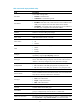
NQA configuration commands NQA client configuration commands advantage-factor Use advantage-factor to configure the advantage factor that is used to count Mean Opinion Scores (MOS) and Calculated Planning Impairment Factor (ICPIF) values. Use undo advantage-factor to restore the default. Syntax advantage-factor factor undo advantage-factor Default The advantage factor is 0.
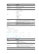
Syntax codec-type { g711a | g711u | g729a } undo codec-type Default The codec type for the voice operation is G.711 A-law. Views Voice operation view Default command level 2: System level Parameters g711a: Specifies G.711 A-law codec type. g711u: Specifies G.711 μ-law codec type g729a: Specifies G.729 A-law codec type. Examples # Configure the codec type for the voice operation as g729a.
If the payload length is greater than the string length, the system fills the payload with the string cyclically until the payload is full. For example, if you configure the string as abcd and the payload size as 6 bytes, abcdab is filled. • How the string is filled varies with operation types: • For the ICMP echo operation, the string fills the whole payload of ICMP echo requests.
Test type Codec type Default value (in bytes) Voice G.711 μ-law 172 Voice G.729 A-law 32 Configure the size of the payload in each probe packet properly. If the traffic amount is large in the network, configure a smaller payload size to reduce network burden. If runt packets are required to be transmitted in the network, configure a bigger payload size to avoid packet loss. Examples # Configure the size of the payload in each ICMP echo request as 80 bytes.
Syntax destination ip ip-address undo destination ip Default No destination IP address is configured for the operation. Views DLSw operation view, FTP operation view, DNS operation view, HTTP operation view, ICMP echo operation view, SNMP operation view, TCP operation view, UDP echo operation view, UDP jitter operation view, voice operation view Default command level 2: System level Parameters ip-address: Specifies the destination IP address of the operation.
Examples # Configure the destination port number of the UDP echo operation as 9000. system-view [Sysname] nqa entry admin test [Sysname-nqa-admin-test] type udp-echo [Sysname-nqa-admin-test-udp-echo] destination port 9000 display nqa history Use display nqa history to display the history records of the specified or all NQA operations.
4 328 Succeeded 2012-04-29 20:54:24.5 3 328 Succeeded 2012-04-29 20:54:24.1 2 328 Succeeded 2012-04-29 20:54:23.8 1 328 Succeeded 2012-04-29 20:54:23.4 Table 23 Command output Field Description Index History record number. Response Round-trip time if the operation succeeds, timeout time upon timeout, or 0 if the operation cannot be completed (in milliseconds). Status value of test results: • Succeeded. Status • Unknown error. • Internal error. • Timeout.
Usage guidelines If the threshold type is average value, or the monitored performance metric is ICPIF or MOS in the voice operation, the monitoring results are invalid. The monitoring results are accumulated after the NQA operation starts and are not cleared after the operation completes. Examples # Display the monitoring results of all reaction entries of the ICMP echo operation with the administrator name admin and the operation tag test.
Monitored performance metric Threshold type Collect data in Checked Num Over-threshold Num accumulate Probes after the operation starts. Number of finished probes after the operation starts. Number of probe failures after the operation starts. consecutive Probes after the operation starts. Number of finished probes after the operation starts. Number of probe failures after the operation starts. accumulate Packets sent after the operation starts.
|: Filters command output by specifying a regular expression. For more information about regular expressions, see System Management Configuration Guide. begin: Displays the first line that matches the specified regular expression and all lines that follow. exclude: Displays all lines that do not match the specified regular expression. include: Displays all lines that match the specified regular expression. regular-expression: Specifies a regular expression, a case-sensitive string of 1 to 256 characters.
# Display the result of the voice operation. display nqa result admin test NQA entry (admin admin, tag test) test results: Destination IP address: 192.168.1.42 Send operation times: 1000 Receive response times: 0 Min/Max/Average round trip time: 0/0/0 Square-Sum of round trip time: 0 Last succeeded probe time: 0-00-00 00:00:00.
Field Description Min/Max/Average round trip time Minimum/maximum/average round-trip time in milliseconds. Square-Sum of round trip time Square sum of round-trip time. Last succeeded probe time Time when the last successful operation was finished. Packet loss in test Average packet loss ratio. Min positive SD Minimum positive jitter from source to destination. Min positive DS Minimum positive jitter from destination to source.
Field Description Min DS delay Minimum delay from destination to source. Number of SD delay Number of delays from source to destination. Number of DS delay Number of delays from destination to source. Sum of SD delay Sum of delays from source to destination. Sum of DS delay Sum of delays from destination to source. Square sum of SD delay Square sum of delays from source to destination. Square sum of DS delay Square sum of delays from destination to source.
If a reaction entry is configured, the command displays the monitoring results of the reaction entry in the period specified by the statistics internal command. If the threshold type is average value or the monitored performance metric is ICPIF or MOS for the voice operation, the monitoring results are invalid. Examples # Display the statistics of the UDP jitter operation. display nqa statistics admin test NQA entry (admin admin, tag test) test statistics: NO. : 1 Destination IP address: 1.1.1.
2 jitter-SD average - - 3 OWD-DS - 100 24 4 OWD-SD - 100 13 5 packet-loss accumulate 0 0 6 RTT accumulate 100 52 # Display the statistics of the voice operation. display nqa statistics admin test NQA entry (admin admin, tag test) test statistics: NO. : 1 Destination IP address: 1.1.1.2 Start time: 2012-01-01 09:33:45.
Max ICPIF value: 0 Min ICPIF value: 0 Reaction statistics: Index Checked Element Threshold Type Checked Num Over-threshold Num 1 ICPIF - - - 2 MOS - - - Table 27 Command output Field Description No. Statistics group number. Destination IP address IP address of the destination. Start time Time when the operation started. Life time Operation duration in seconds. Send operation times Number of probe packets sent. Receive response times Number of response packets received.
Field Description Positive DS square sum Square sum of positive jitters from destination to source. Min negative SD Minimum absolute value among negative jitters from source to destination. Min negative DS Minimum absolute value among negative jitters from destination to source. Max negative SD Maximum absolute value among negative jitters from source to destination. Max negative DS Maximum absolute value among negative jitters from destination to source.
Field Description Threshold Type Threshold type. Checked Num Number of targets that have been monitored for data collection. Over-threshold Num Number of threshold violations. Table 28 Description of the threshold monitoring fields Monitored performance metric probe-duration Threshold type Collect data in Checked Num Over-threshold Num accumulate Probes in the counting interval. Number of finished probes in the counting interval.
Monitored performance metric Threshold type Collect data in Checked Num Over-threshold Num packet-loss accumulate Packets sent in the counting interval. Number of packets sent in the counting interval. Number of packet loss in the counting interval. Related commands statistics interval filename Use filename to specify a file to be transferred between the FTP server and the FTP client. Use undo filename to restore the default. Syntax filename filename undo filename Default No file is specified.
Default The interval between two consecutive voice operations is 60000 milliseconds, and the interval between two consecutive operations of other types is 0 milliseconds. Views Any NQA operation view Default command level 2: System level Parameters interval: Specifies the interval in milliseconds between two consecutive operations, in the range of 0 to 604800000. An interval of 0 sets the operation to be performed only once, and to not collect any statistics.
Related commands display nqa history history-record keep-time Use history-record keep-time to set the lifetime of history records in the NQA operation. Use undo history-record keep-time to restore the default. Syntax history-record keep-time keep-time undo history-record keep-time Default The history records in an NQA operation are kept for 120 minutes. Views Any NQA operation view Default command level 2: System level Parameters keep-time: Specifies how long the history records can be saved.
Views Any NQA operation view Default command level 2: System level Parameters number: Specifies the maximum number of history records that can be saved in an NQA operation. The value is in the range of 0 to 50. Usage guidelines If the number of history records in an NQA operation exceeds the maximum number, the earliest history record is removed. Examples # Configure the maximum number of history records that can be saved in an NQA operation as 10.
mode Use mode to set the data transmission mode for the FTP operation. Use undo mode to restore the default. Syntax mode { active | passive } undo mode Default The data transmission mode use by the FTP operation is active. Views FTP operation view Default command level 2: System level Parameters active: Sets the data transmission mode to active for the FTP operation. In this mode, the FTP server initiates a connection request. passive: Sets the data transmission mode to passive for the FTP operation.
Parameters ip-address: Specifies the IP address of the next hop. Usage guidelines If multiple paths exist between the source and destination devices, you can specify the device directly connected to the source device on one of the paths as the next hop for the ICMP echo operation. Examples # Configure the next hop IP address as 10.1.1.1 for the ICMP echo operation. system-view [Sysname] nqa entry admin test [Sysname-nqa-admin-test] type icmp-echo [Sysname-nqa-admin-test-icmp-echo] next-hop 10.1.
nqa agent enable Use nqa agent enable to enable the NQA client. Use undo nqa agent enable to disable the NQA client and stop all the operations being performed. Syntax nqa agent enable undo nqa agent enable Default The NQA client is enabled. Views System view Default command level 2: System level Examples # Enable the NQA client.
system-view [Sysname] nqa agent max-concurrent 5 nqa schedule Use nqa schedule to configure the scheduling parameters for an NQA operation. Use undo nqa schedule to stop the operation.
operation (FTP operation view) Use operation to specify the operation type for the HTTP operation. Use undo operation to restore the default. Syntax operation { get | put } undo operation Default The operation type is get. Views FTP operation view Default command level 2: System level Parameters get: Gets a file from the FTP server. put: Transfers a file to the FTP server. Usage guidelines When you execute the put command, the NQA client creates a file named file-name of fixed size on the FTP server.
Default command level 2: System level Parameters get: Gets data from the HTTP server. post: Transfers data to the HTTP server. Examples # Specify the operation type for the HTTP operation as post. system-view [Sysname] nqa entry admin test [Sysname-nqa-admin-test] type http [Sysname-nqa-admin-test-http] operation post operation interface Use operation interface to specify the interface to perform the DHCP operation. The specified interface must be up.
password (FTP operation view) Use password to configure a password used to log in to the FTP server. Use undo password to remove the configured password. Syntax password [ cipher | simple ] password undo password Default No password is configured for logging in to the FTP server. For secrecy, all keys, including keys configured in plain text, are saved in cipher text. Views FTP operation view Default command level 2: System level Parameters cipher: Sets a ciphertext password.
Views DHCP operation view, DNS operation view, DLSw operation view, FTP operation view, HTTP operation view, ICMP echo operation view, SNMP operation view, TCP operation view, UDP echo operation view, UDP jitter operation view Default command level 2: System level Parameters times: Specifies the probe times, in the range of 1 to 15.
probe packet-number Use probe packet-number to configure the number of packets to be sent in one UDP jitter or voice probe. Use undo probe packet-number to restore the default. Syntax probe packet-number packet-number undo probe packet-number Default An UDP jitter probe sends 10 packets and a voice probe sends 1000 packets. Views UDP jitter operation view, voice operation view Default command level 2: System level Parameters packet-number: Specifies the number of packets to be sent per probe.
Parameters packet-timeout: Specifies the timeout time in milliseconds for waiting for a response in the UDP jitter or voice operation. The value is in the range of 10 to 3600000. Examples # Configure the timeout time for waiting for a response in the UDP jitter operation as 100 milliseconds.
Use undo reaction to delete the specified reaction entry. Syntax reaction item-number checked-element [ action-type { none | trap-only } ] icpif threshold-value upper-threshold lower-threshold undo reaction item-number Default No reaction entry for monitoring ICPIF values is configured. Views Voice operation view Default command level 2: System level Parameters item-number: Specifies a reaction entry ID in the range of 1 to 10. threshold-value: Specifies threshold values.
Syntax reaction item-number checked-element { jitter-ds | jitter-sd } threshold-type { accumulate accumulate-occurrences | average } threshold-value upper-threshold lower-threshold [ action-type { none | trap-only } ] undo reaction item-number Default No reaction entry for monitoring one-way jitter is configured. Views UDP jitter operation view, voice operation view Default command level 2: System level Parameters item-number: Specifies a reaction entry ID in the range of 1 to 10.
[Sysname-nqa-admin-test] type udp-jitter [Sysname-nqa-admin-test-udp-jitter] reaction 1 checked-element jitter-ds threshold-type average threshold-value 50 5 action-type trap-only # Create reaction entry 2 for monitoring the destination-to-source jitter of UDP jitter probe packets. Set the upper threshold to 50 milliseconds, and the lower threshold to 5 milliseconds. Before the NQA operation starts, the initial state of the reaction entry is invalid.
Usage guidelines For the MOS threshold, the number is expressed in three digits representing ones, tenths, and hundredths. For example, to express a MOS threshold of 1, enter 100. Examples # Create reaction entry 1 for monitoring the MOS value of the voice operation. Set the upper threshold to 2, and lower threshold to 1. Before the NQA operation starts, the initial state of the reaction entry is invalid. After the operation, the MOS value is checked.
No actions can be configured for a reaction entry of monitoring one-way delays. The monitoring results and statistics can be displayed with the display nqa reaction counters and display nqa statistics commands. Examples # Create reaction entry 1 for monitoring the destination-to-source delay of every UDP jitter packet. Set the upper threshold to 50 milliseconds and lower threshold to 5 milliseconds. Before the NQA operation starts, the initial state of the reaction entry is invalid.
Examples # Create reaction entry 1 for monitoring packet loss in the UDP jitter operation. Before the NQA operation starts, the initial state of the reaction entry is invalid. After the operation, lost packets are checked. If the total number of lost packets exceeds 100 (included), the state of the reaction entry is set to over-threshold. Otherwise, the state is set to below-threshold. Once the state of the reaction entry changes, a trap message is generated and sent to the NMS.
action-type: Specifies what action to be triggered. The default action is none. none: Specifies the action of only displaying results on the terminal display. trap-only: Specifies the action of displaying results on the terminal display and meanwhile sending SNMP trap messages to the NMS. This keyword is not supported for the DNS operation. Usage guidelines Only successful operations are monitored. Failed operations are not counted.
Use undo reaction to delete the specified reaction entry. Syntax reaction item-number checked-element probe-fail threshold-type { accumulate accumulate-occurrences | consecutive consecutive-occurrences } [ action-type { none | trap-only } ] undo reaction item-number Default No reaction entry for monitoring probe failures is configured.
[Sysname-nqa-admin-test-icmp-echo] reaction 2 checked-element probe-fail threshold-type consecutive 10 action-type trap-only reaction checked-element probe-fail (for trigger) Use reaction checked-element probe-fail to configure a reaction entry for monitoring the probe failures. This command is applicable to trap messages only. You cannot edit a reaction entry. To change the attributes in a reaction entry, use undo reaction to delete the entry first and then configure a new one.
reaction checked-element rtt Use reaction checked-element rtt to configure a reaction entry for monitoring packet round-trip time. You cannot edit a reaction entry. To change the attributes in a reaction entry, use undo reaction to delete the entry first and then configure a new one. Use undo reaction to delete the specified reaction entry.
[Sysname] nqa entry admin test [Sysname-nqa-admin-test] type udp-jitter [Sysname-nqa-admin-test-udp-jitter] reaction 1 checked-element rtt threshold-type average threshold-value 50 5 action-type trap-only # Create reaction entry 2 for monitoring the round-trip time of UDP jitter probe packets. Set the upper threshold to 50 milliseconds, and lower threshold to 5 milliseconds. Before the NQA operation starts, the initial state of the reaction entry is invalid.
Examples # Configure the system to send a trap if the number of consecutive probe failures in an ICMP echo operation is greater than or equal to 5. system-view [Sysname] nqa entry admin test [Sysname-nqa-admin-test] type icmp-echo [Sysname-nqa-admin-test-icmp-echo] reaction trap probe-failure 5 resolve-target Use resolve-target to set the domain name for the DNS operation. Use undo resolve-target to restore the default.
Views DLSw operation view, DNS operation view, FTP operation view, HTTP operation view, ICMP echo operation view, SNMP operation view, TCP operation view, UDP echo operation view, UDP jitter operation view, voice operation view Default command level 2: System level Usage guidelines When the routing table bypass function is enabled, the routing table is not searched, and the packet is sent directly to the destination in a directly connected network. Examples # Enable the routing table bypass function.
[Sysname] nqa entry admin test [Sysname-nqa-admin-test] type icmp-echo [Sysname-nqa-admin-test-icmp-echo] source interface gigabitethernet 0/1 Related commands source ip source ip Use source ip to configure the source IP address of probe packets. The specified source IP address must be the IP address of a local interface. The local interface must be up. Otherwise, no probe packets can be sent out. Use undo source ip to remove the configured source address.
source port Use source port to configure the source port of probe packets. Use undo source port to remove the configured port number. Syntax source port port-number undo source port Default No source port number is configured. Views SNMP operation view, UDP echo operation view, UDP jitter operation view, voice operation view Default command level 2: System level Parameters port-number: Specifies the source port number of probe packets, in the range of 1 to 50000.
Usage guidelines This command is not available for the DHCP operation. Examples # Configure the hold time of statistics groups as 3 minutes. system-view [Sysname] nqa entry admin test [Sysname-nqa-admin-test] type icmp-echo [Sysname-nqa-admin-test-icmp-echo] statistics hold-time 3 statistics max-group Use statistics max-group to configure the maximum number of statistics groups that can be saved. Use undo statistics max-group to restore the default.
Syntax statistics interval interval undo statistics interval Default The interval is 60 minutes. Views DLSw operation view, DNS operation view, FTP operation view, HTTP operation view, ICMP echo operation view, SNMP operation view, TCP operation view, UDP echo operation view, UDP jitter operation view, voice operation view Default command level 2: System level Parameters interval: Specifies the interval in minutes for collecting statistics for an NQA operation, in the range of 1 to 35791394.
Parameters value: Specifies the ToS value in the IP packet header of probe packets, in the range of 0 to 255. Examples # Configure the ToS value in an IP packet header of probe packets as 1. system-view [Sysname] nqa entry admin test [Sysname-nqa-admin-test] type icmp-echo [Sysname-nqa-admin-test-icmp-echo] tos 1 ttl Use ttl to specify the TTL for probe packets. Use undo ttl to restore the default. Syntax ttl value undo ttl Default The TTL for probe packets is 20.
Default No test type is specified. Views NQA operation view Default command level 2: System level Parameters dhcp: Specifies the DHCP operation type. dlsw: Specifies the DLSw operation type. dns: Specifies the DNS operation type. ftp: Specifies the FTP operation type. http: Specifies the HTTP operation type. icmp-echo: Specifies the ICMP echo operation type. snmp: Specifies the SNMP operation type. tcp: Specifies the TCP operation type. udp-echo: Specifies the UDP echo operation type.
Usage guidelines The character string of the configured URL cannot contain spaces. Examples # Configure the website URL that the HTTP operation visits as /index.htm. system-view [Sysname] nqa entry admin test [Sysname-nqa-admin-test] type http [Sysname-nqa-admin-test-http] url /index.htm username (FTP operation view) Use username to configure a username used to log in to the FTP server. Use undo username to remove the username.
undo vpn-instance Default The ICMP echo operation applies to the public network. Views ICMP echo operation view Default command level 2: System level Parameters vpn-instance-name: Specifies the name of the VPN, a case-sensitive string of 1 to 31 characters. Examples # Specify vpn1 as the VPN.
display nqa server status nqa server is: enabled tcp-connect: IP Address Port Status 2.2.2.2 2000 active udp-echo: IP Address Port Status 3.3.3.3 3000 inactive Table 29 Command output Field Description tcp-connect TCP connect listening service. udp-echo UDP echo listening service. IP Address IP address specified for the TCP/UDP listening service on the NQA server. Port Port number of the TCP/UDP listening service on the NQA server.
nqa server tcp-connect Use nqa server tcp-connect to configure a listening service to enable the NQA server to listen and respond on the specified IP address and port. Use undo nqa server tcp-connect to remove the TCP listening service. Syntax nqa server tcp-connect ip-address port-number undo nqa server tcp-connect ip-address port-number Views System view Default command level 2: System level Parameters ip-address: Specifies the IP address for the TCP connect listening service.
Default command level 2: System level Parameters ip-address: Specifies the IP address for the UDP echo listening service. port-number: Specifies the port number for the UDP listening service, in the range of 1 to 50000. Usage guidelines Configure the command on the NQA server for the UDP jitter, UDP echo, and voice operations only. The IP address and port number must be consistent with those configured on the NQA client and must be different from those of an existing UDP listening service.
Interface backup configuration commands display standby flow Use display standby flow to display statistics about traffic on the active interfaces participating in load balancing. Syntax display standby flow [ | { begin | exclude | include } regular-expression ] Views Any view Default command level 1: Monitor level Parameters |: Filters command output by specifying a regular expression. For more information about regular expressions, see System Management Configuration Guide.
Field Description OutFlow(Octets) Sum of the octets sent on the active interface during the last interval. BandWidth(b/s) Bandwidth of the active interface. UsedBandWidth(b/s) Actual bandwidth for the active interface participating in load balancing during the last interval. display standby state Use display standby state to display the state information of the active and standby interfaces.
State Active interface Standby interface STANDBY N/A The state of the standby interfaces when the active interface is functioning. Data transmission is disabled. Table 32 Backup state of the active interface State Description MUP The active interface is working properly for data transmission. MUPDELAY The active interface is experiencing a delay before it transits from the non-working state to the working state to take over. At this time, the standby interface is still active.
State Description TO-HYPNOTIZE The standby interface is transiting from the working state to the non-working state after the traffic size decreases below the lower backup load balancing threshold. In this state, the standby interface is still working. TO-WAKE The standby interface is transiting from the non-working state to the working state after the traffic size increases above the upper backup load balancing threshold. Null State other than the above three.
standby interface Use standby interface to specify a standby interface for the current interface. Use undo standby interface to remove the specified standby interface. Syntax standby interface interface-type interface-number [ priority ] undo standby interface interface-type interface-number Default No standby interface is specified. Views Interface view Default command level 2: System level Parameters interface-type interface-number: Specifies an interface by its type and number.
Views Interface view Default command level 2: System level Parameters enable-threshold: Specifies the upper load balancing threshold. It indicates the percentage of the available active-interface bandwidth that the traffic load must exceed for the standby interface to come up for load balancing. It ranges from 1 to 99. disable-threshold: Specifies the lower load balancing threshold.
Default Switchover delays on the active and standby interfaces are 0, indicating immediate switch without any delay. Views Interface view Default command level 2: System level Parameters enable-delay: Specifies switchover delay from the active interface to the standby interface. It ranges from 0 to 65535 seconds. disable-delay: Specifies switchover delay from the standby interface to the active interface. It ranges from 0 to 65535 seconds.
Parameters interval: Specifies flow check interval, which ranges from 30 to 600 seconds. Usage guidelines Use this command after standby interfaces are specified. Examples # Configure load balancing, backup bandwidth and flow check interval on interface GigabitEthernet 0/1 as 60 seconds.
Syntax standby track track-entry-number undo standby track Default An interface is not associated with a track entry. Views Interface view Default command level 2: System level Parameters track-entry-number: Specifies a track entry to be monitored by its number, which ranges from 1 to 1024. Usage guidelines This command and the standby interface command cannot be configured at the same time.
Support and other resources Contacting HP For worldwide technical support information, see the HP support website: http://www.hp.
Conventions This section describes the conventions used in this documentation set. Command conventions Convention Description Boldface Bold text represents commands and keywords that you enter literally as shown. Italic Italic text represents arguments that you replace with actual values. [] Square brackets enclose syntax choices (keywords or arguments) that are optional. { x | y | ... } Braces enclose a set of required syntax choices separated by vertical bars, from which you select one.
Network topology icons Represents a generic network device, such as a router, switch, or firewall. Represents a routing-capable device, such as a router or Layer 3 switch. Represents a generic switch, such as a Layer 2 or Layer 3 switch, or a router that supports Layer 2 forwarding and other Layer 2 features. Represents a security product, such as a firewall, a UTM, or a load-balancing or security card that is installed in a device.
Index ACDFHIMNOPRSTUVW filename,82 A frequency,82 advantage-factor,64 H C history-record enable,83 codec-type,64 history-record keep-time,84 D history-record number,84 data-fill,65 http-version,85 data-size,66 I description (any NQA operation view),67 ipc performance enable,56 destination ip,67 destination port,68 M dhbk configuration-backup,45 mode,86 dhbk enable,45 N dhbk ignore-version-check,46 next-hop,86 dhbk interface vlan,46 nqa,87 display dhbk status,47 nqa agent enable,8
reaction checked-element mos,98 track nqa,59 reaction checked-element packet-loss,100 ttl,113 reaction checked-element probe-duration,101 type,113 reaction checked-element probe-fail (for trap),102 U reaction checked-element probe-fail (for trigger),104 url,114 reaction checked-element rtt,105 username (FTP operation view),115 reaction trap,106 reset ipc performance,57 V reset vrrp ipv6 statistics,34 vpn-instance (ICMP echo operation view),115 reset vrrp statistics,13 vrrp ipv6 method,35 r