HP Load Balancing Module High Availability Configuration Guide Part number: 5998-4220 Software version: Feature 3221 Document version: 6PW100-20130326
Legal and notice information © Copyright 2013 Hewlett-Packard Development Company, L.P. No part of this documentation may be reproduced or transmitted in any form or by any means without prior written consent of Hewlett-Packard Development Company, L.P. The information contained herein is subject to change without notice.
Contents High availability overview··········································································································································· 1 Availability requirements ·················································································································································· 1 Availability evaluation ········································································································································
Enabling automatic configuration synchronization···························································································· 82 Configuring a failover interface and a backup VLAN ······················································································ 82 Displaying and maintaining stateful failover ······································································································ 83 Stateful failover configuration example ····································
Configuring the NQA statistics function ··········································································································· 128 Configuring NQA history records saving function ·························································································· 128 Scheduling an NQA operation·························································································································· 129 Displaying and maintaining NQA ································
High availability overview Because communication interruptions can seriously affect widely-deployed value-added services such as IPTV and video conference, basic network infrastructures must be able to provide high availability. The following are the effective ways to improve availability: • Increasing fault tolerance. • Speeding up fault recovery. • Reducing impact of faults on services.
MTTR = fault detection time + hardware replacement time + system initialization time + link recovery time + routing time + forwarding recovery time. A smaller value of each item means a smaller MTTR and a higher availability. High availability technologies Increasing MTBF or decreasing MTTR can enhance the availability of a network. The high availability technologies described in this section meet the level 2 and level 3 high availability requirements in the aspect of decreasing MTTR.
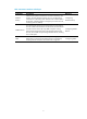
Table 3 Protection switchover technologies Technology Introduction Reference Interface backup Interface backup allows interfaces on one device to back up one another. The main interface transmits services, and the backup interfaces are in the backup state. When the main interface fails or the link fails, a backup interface is brought up to transmit services, increasing network reliability.
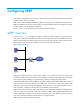
Configuring VRRP The interfaces that VRRP involves can be only Layer 3 Ethernet interfaces and subinterfaces and VLAN interfaces unless otherwise specified. VRRP versions include VRRPv2 and VRRPv3. VRRPv2 is based on IPv4, and VRRPv3 is based on IPv6. VRRPv2 and VRRPv3 are the same in functionality, but apply to different network environments. The Web interface supports only configuration of VRRPv2. The term "router" in this document refers to both routers and LB modules.
• Standard mode—Includes IETF VRRPv2 for IPv4 and VRRPv3 for IPv6. For more information, see "VRRP standard mode." • Load balancing mode—Extends the standard mode and realizes load balancing. For more information, see "VRRP load balancing mode." VRRP standard mode VRRP group VRRP combines a group of routers (including a master and multiple backups) on a LAN into a virtual router called VRRP group. A VRRP group has the following features: • A virtual router has a virtual IP address.
VRRP determines the role (master or backup) of each router in a VRRP group by priority. A router with a higher priority is more likely to become the master. VRRP priority is in the range of 0 to 255, and the greater the number, the higher the priority. Priorities 1 to 254 are configurable. Priority 0 is reserved for special uses and priority 255 is for the IP address owner.
Packet format The master periodically multicasts VRRP packets to declare its presence. VRRP packets are also used for checking the parameters of the virtual router and electing the master. VRRP packets are encapsulated in IP packets, with the protocol number being 112. Figure 3 shows the VRRPv2 packet format and Figure 4 shows the VRRPv3 packet format.
• Auth Type—Authentication type. 0 means no authentication, 1 means simple text authentication, and 2 means MD5 authentication. VRRPv3 does not support MD5 authentication. • Adver Int—Interval for sending advertisement packets. For VRRPv2, the interval is in seconds and defaults to 1. For VRRPv3, the interval is in centiseconds and defaults to 100. • Checksum—16-bit checksum for validating the data in VRRP packets. • IP Address/IPv6 Address—Virtual IPv4 or IPv6 address entry of the VRRP group.
If the uplink fails, hosts in the LAN cannot access external networks through the router. The state of the monitored track entry is negative and the priority of the router decreases by a specified value. Then, a higher priority router in the VRRP group becomes the master to maintain the proper communication between the hosts in the LAN and external networks. { Monitor the master on a backup. When the master fails, the backup immediately takes over to maintain normal communication.
Figure 6 VRRP in load sharing mode A router can be in multiple VRRP groups and hold a different priority in a different group. As shown in Figure 6, the following VRRP groups are present: { VRRP group 1—Router A is the master. Router B and Router C are the backups. { VRRP group 2—Router B is the master. Router A and Router C are the backups. { VRRP group 3—Router C is the master. Router A and Router B are the backups.
In an IPv4 network, a load-balanced VRRP group works as follows: 1. The master assigns virtual MAC addresses to all members, including itself. This example assumes that the virtual IP address of the VRRP group is 10.1.1.1/24, Router A is the master, and Router B is the backup. Router A assigns 000f-e2ff-0011 to itself and 000f-e2ff-0012 to Router B. Figure 7 Virtual MAC address assignment 2.
Figure 9 Sending packets to different routers for forwarding Virtual forwarder 1. Creating a virtual forwarder Virtual MAC addresses enable traffic distribution across the routers in a VRRP group. To enable the routers in the VRRP group to forward the packets, be sure to create virtual forwarders (VFs) on the routers. Each VF associates with a virtual MAC address in the VRRP group and forwards packets sent to this virtual MAC address. VFs are created on the routers in a VRRP group, as follows: a.
{ { 3. On a router that does not own the VF, if the weight of the VF is higher than or equal to the lower limit of failure, the priority of the VF is weight/(number of local AVFs +1). If the weight of the VF is lower than the lower limit of failure, the priority of the VF is 0. VF backup The VFs corresponding to a virtual MAC address on different routers in the VRRP group back up each other.
can share traffic load if the VF owner resumes normal operation within this time. When this timer times out, the master stops using the virtual MAC address corresponding to the failed AVF to respond to ARP/ND requests from the hosts. { 5. Timeout Timer—Duration that the new AVF takes over the VF owner. Before this timer times out, all the routers in the VRRP group keep the failed AVF, and the new AVF forwards the packets destined for the virtual MAC address corresponding to the failed AVF.
Configuring IPv4 VRRP Configuring IPv4 VRRP in the Web interface Recommended configuration procedure Step Remarks Required. Create a VRRP group on a VRRP interface and configure the virtual IP address. IMPORTANT: 1. Creating a VRRP group • Before creating a VRRP group on an interface, you should first configure an IP address for the interface and make sure that the virtual IP address to be configured is in the same network segment as the IP address of the interface.
Figure 12 VRRP group page On the VRRP group configuration page, Run Priority indicates current priority of the router, which changes according to the status of the tracked interface or track entry (if configured). Status indicates status of the router (master, backup, or initialize) in the VRRP group. 3. Click Add. The page for creating a VRRP group appears. Figure 13 Creating a VRRP group 4. Enter the group number of the VRRP group (VRID). 5.
6. Click Apply. Configuring a VRRP group 1. Select High Availability > VRRP from the navigation tree. The VRRP interfaces page appears. 2. Click the icon corresponding to the interface to be configured. The VRRP group page appears. 3. Click the icon corresponding to the VRRP group to be configured. The page for modifying the VRRP group configuration appears. Figure 14 Modifying the VRRP group configuration 4. Configure the parameters as described in Table 4.
Item Description Configure the virtual IP address of the VRRP group. If an interface connects to multiple subnets, you can configure multiple virtual IP addresses for the VRRP group to implement router backup on different subnets. IMPORTANT: • The virtual IP address cannot be 0.0.0.0, 255.255.255.255, a loopback address, any other invalid IP address (like 0.0.0.1), or an address that does not belong to class A, B or C.
Item Description Set the interval at which the master sends VRRP advertisements. Advertise Time Excessive traffic or different timer setting on routers can cause the Backup timer to time out abnormally and trigger a change of the state. To solve this problem, you can prolong the time interval to send VRRP packets. IMPORTANT: Routers in the same VRRP group must use the same setting of advertisement interval. 5. Click Display Track Config to expand the configuration items of the tracking function.
Table 5 Configuration items Item Description Object Configure the track object function by adding the Track object to be monitored and the processing method: • Object—Specify the serial number of the Track object to be monitored. You can specify an uncreated object. Reduced Priority Track Object • Reduced Priority—If the status of the monitored Track object changes to negative, the priority of the router decreases by a specified value.
Task Remarks Optional. Configuring VF tracking This configuration applies to only VRRP load balancing mode. Configuring VRRP packet attributes Optional. Enabling the trap function for VRRP Optional. Configuring a VRRP working mode A VRRP group operates in one of the following modes: • Standard mode—Only the master can forward packets. • Load balancing mode—All members that have an AVF can forward packets.
Step Command Remarks 1. Enter system view. system-view N/A 2. Specify the type of MAC addresses mapped to virtual IP addresses. vrrp method { real-mac | virtual-mac } Optional. Virtual MAC address by default. Creating a VRRP group and configuring virtual IP address 1. Configuration guidelines • You can configure multiple virtual IP addresses for the VRRP group on an interface that connects to multiple subnets for router backup on different subnets.
Step Command Remarks 2. Enter the specified interface view. interface interface-type interface-number N/A 3. Create a VRRP group and configure a virtual IP address for the VRRP group. vrrp vrid virtual-router-id virtual-ip virtual-address VRRP group is not created by default. NOTE: You can configure a maximum of 16 VRRP groups on an interface and a maximum of 16 virtual IP addresses in a VRRP group. Configuring router priority, preemptive mode and tracking function 1.
Step Command Remarks 5. Configure the interface to be tracked. vrrp vrid virtual-router-id track interface interface-type interface-number [ reduced priority-reduced ] Optional. 6. Configure VRRP to track a specified track entry. vrrp vrid virtual-router-id track track-entry-number [ reduced priority-reduced | switchover ] Optional. By default, no interface is being tracked. By default, VRRP is not configured to track a specified track entry. Configuring VF tracking 1.
Step Command Remarks • Configure the VF tracking function to monitor a specified track entry and specify the value by which the weight decreases: vrrp vrid virtual-router-id weight track track-entry-number [ reduced weight-reduced ] Configure VF tracking. 3. • Configure the VF tracking function to monitor an AVF on a specified router: vrrp vrid virtual-router-id track track-entry-number forwarder-switchover member-ip ip-address Use either approach.
Step 4. Configure the time interval for the master in the VRRP group to send VRRP advertisements. Command Remarks vrrp vrid virtual-router-id timer advertise adver-interval Optional. 1 second by default. Optional. 5. Disable TTL check on VRRP packets. vrrp un-check ttl By default, TTL check on VRRP packets is enabled. You do not need to create a VRRP group before executing this command.
Configuring IPv6 VRRP IPv6 VRRP can be configured only at the CLI. IPv6 VRRP configuration task list Task Remarks Configuring a VRRP working mode Optional. Specifying the type of MAC addresses mapped to virtual IPv6 addresses Optional. This configuration does not apply to VRRP load balancing mode. Creating a VRRP group and configuring a virtual IPv6 address Required. Configuring router priority, preemptive mode and tracking function Optional. Optional.
To specify the type of MAC addresses mapped to virtual IPv6 addresses: Step Command Remarks 1. Enter system view. system-view N/A 2. Specify the type of MAC addresses mapped to virtual IPv6 addresses. vrrp ipv6 method { real-mac | virtual-mac } Optional. Virtual MAC address by default. Creating a VRRP group and configuring a virtual IPv6 address When creating a VRRP group, configure a virtual IPv6 address for the VRRP group. You can configure multiple virtual IPv6 addresses for a VRRP group.
Step Command Remarks No VRRP group is created by default. 3. Create a VRRP group and configure its virtual IPv6 address, which is a link local address. vrrp ipv6 vrid virtual-router-id virtual-ip virtual-address link-local 4. Configure the VRRP group with a virtual IPv6 address, which is a global unicast address. vrrp ipv6 vrid virtual-router-id virtual-ip virtual-address The first virtual IPv6 address of the VRRP group must be a link local address.
Step Command Remarks Optional. Configure the router in the VRRP group to operate in preemptive mode and configure preemption delay of the VRRP group. vrrp ipv6 vrid virtual-router-id preempt-mode [ timer delay delay-value ] The router in the VRRP group operates in preemptive mode and the preemption delay is zero seconds by default. 5. Configure the interface to be tracked. vrrp ipv6 vrid virtual-router-id track interface interface-type interface-number [ reduced priority-reduced ] Optional. 6.
Step Command Remarks • Configure the VF tracking function Configure VF tracking. 3. to monitor a specified track entry and specify the value by which the weight decreases: vrrp ipv6 vrid virtual-router-id weight track track-entry-number [ reduced weight-reduced ] • Configure the VF tracking function to monitor an AVF on a specified router: vrrp ipv6 vrid virtual-router-id track track-entry-number forwarder-switchover member-ip ipv6-address Use either approach.
Displaying and maintaining IPv6 VRRP Task Command Remarks Display VRRP group status. display vrrp ipv6 [ verbose ] [ interface interface-type interface-number [ vrid virtual-router-id ] ] [ | { begin | exclude | include } regular-expression ] Available in any view. Display VRRP group statistics. display vrrp ipv6 statistics [ interface interface-type interface-number [ vrid virtual-router-id ] ] [ | { begin | exclude | include } regular-expression ] Available in any view.
Figure 16 Network diagram Configuring Device A 1. Configure the IP address of each interface. (Details not shown.) 2. Create VRRP group 1 on GigabitEthernet 0/1 and configure the virtual IP address as 202.38.160.111: a. Select High Availability > VRRP from the navigation tree. b. Click the icon corresponding to GigabitEthernet 0/1. The VRRP group page appears. c. Click Add. The page for creating a VRRP group appears. d. Enter 1 in the VRID field and 202.38.160.
e. Select Simple from the Authentication field. f. Enter hello in the Key field. g. Enter 5 in the Advertise Time field. h. Click Display Track Config. i. Select GigabitEthernet0/2 from the Interface field, enter 30 in the Reduced Priority field, and then click Add to add the interface to the list box of tracked interface. j. Click Apply. Figure 18 Configuring VRRP group attributes Configuring Device B 1. Configure the IP address of each interface. (Details not shown) 2.
Figure 19 Creating VRRP group 1 3. Configure VRRP group attributes: a. On the VRRP group page of GigabitEthernet 0/1, click the group 1. icon corresponding to VRRP b. Select Preemptive from the Preempt Mode field. c. Enter 5 in the Delay field. d. Select Simple from the Authentication field. e. Enter hello in the Key field. f. Enter 5 in the Advertise Time field. g. Click Apply.
Single VRRP group configuration example at the CLI Network requirements • Host A needs to access Host B on the Internet, using 202.38.160.111/24 as its default gateway. • LB A and LB B belong to VRRP group 1 with the virtual IP address of 202.38.160.111/24. • If LB A operates properly, packets sent from Host A to Host B are forwarded by LB A. If LB A fails, packets sent from Host A to Host B are forwarded by LB B. Figure 21 Network diagram Configuration procedure 1.
3. Verify the configuration: After the configuration, Host B can be pinged successfully on Host A. To verify your configuration, use the display vrrp verbose command. # Display the detailed information about VRRP group 1 on LB A.
Preempt Mode : Yes Auth Type : None Delay Time Virtual IP : 202.38.160.111 Virtual MAC : 0000-5e00-0101 Master IP : 202.38.160.2 : 5 The output shows that if LB A fails, LB B becomes the master, and packets sent from host A to host B are forwarded by LB B. # After LB A resumes normal operation, use the display vrrp verbose command to display the detailed information about VRRP group 1 on LB A.
Figure 22 Network diagram Configuration procedure 1. Configure LB A: system-view [LBA] interface gigabitethernet0/2 [LBA-GigabitEthernet0/2] ip address 202.38.160.1 255.255.255.0 # Create VRRP group 1 and configure its virtual IP address as 202.38.160.111. [LBA-GigabitEthernet0/2] vrrp vrid 1 virtual-ip 202.38.160.111 # Configure the priority of LB A in the VRRP group as 110, which is higher than that of LB B (100), so that LB A can become the master.
[LBB-GigabitEthernet0/2] vrrp vrid 1 authentication-mode simple hello # Configure the master to send VRRP packets every four seconds. [LBB-GigabitEthernet0/2] vrrp vrid 1 timer advertise 4 # Configure LB B to operate in preemptive mode, so that LB B can become the master after the priority of LB A decreases to a value lower than 100. Configure the preemption delay as five seconds to avoid frequent status switchover. [LBB-GigabitEthernet0/2] vrrp vrid 1 preempt-mode timer delay 5 3.
# If interface GigabitEthernet 0/1 on LB A is not available, the detailed information about VRRP group 1 on LB A is displayed.
Figure 23 Network diagram Configuring Device A 1. Configure the IP address of each interface. (Details not shown.) 2. Create VRRP group 1 on GigabitEthernet 0/1 and configure the virtual IP address as 202.38.160.111: a. Select High Availability > VRRP from the navigation tree. b. Click the icon corresponding to GigabitEthernet 0/1. The VRRP group page appears. c. Click Add. The page for creating a VRRP group appears. d. Enter 1 in the VRID field and 202.38.160.
c. Click Apply. Figure 25 Creating VRRP group 2 4. Set the priority of Device A in VRRP group 1 to 110: a. On the VRRP group page of GigabitEthernet 0/1, click the icon corresponding to VRRP group 1. b. Enter 110 in the Priority field. c. Click Apply. Figure 26 Setting the priority of Device A in VRRP group 1 Configuring Device B The Web interfaces for configuring Device B are similar to those when you configure Device A. The figures are omitted. 1. Configure the IP address of each interface.
The page for creating a VRRP group appears. d. Enter 1 in the VRID field and 202.38.160.111 in the Virtual IP field, and click Add to add the virtual IP address to the Virtual IP Members field. e. Click Apply. 3. Create VRRP group 2 on GigabitEthernet 0/1 and configure the virtual IP address as 202.38.160.112: a. On the VRRP group page of GigabitEthernet 0/1, click Add. b. Enter 2 in the VRID field and 202.38.160.
Figure 27 Network diagram Configuration procedure 1. Configure LB A: system-view [LBA] interface gigabitethernet0/1 [LBA-GigabitEthernet0/1] ip address 202.38.160.1 255.255.255.0 # Create VRRP group 1 and configure its virtual IP address as 202.38.160.111. [LBA-GigabitEthernet0/1] vrrp vrid 1 virtual-ip 202.38.160.111 # Set the priority of LB A in VRRP group 1 to 110, which is higher than that of LB B (100), so that LB A can become the master in VRRP group 1.
Run Mode : Standard Run Method : Virtual MAC Total number of virtual routers : 2 Interface GigabitEthernet0/1 VRID : 1 Adver Timer : 1 Admin Status : Up State : Master Config Pri : 110 Running Pri : 110 Preempt Mode : Yes Delay Time : 0 Auth Type : None Virtual IP : 202.38.160.111 Virtual MAC : 0000-5e00-0101 Master IP : 202.38.160.
The output shows that in VRRP group 1 LB A is the master, LB B is the backup and the host with the default gateway of 202.38.160.111/24 accesses the Internet through LB A. In VRRP group 2 LB A is the backup, LB B is the master and the host with the default gateway of 202.38.160.112/24 accesses the Internet through LB B. NOTE: To implement load balancing between the VRRP groups, be sure to configure the default gateway as 202.38.160.111 or 202.38.160.112 on the hosts on network segment 202.38.160.0/24.
system-view [LBA] vrrp mode load-balance # Create VRRP group 1 and configure its virtual IP address as 10.1.1.1. [LBA] interface gigabitethernet0/1 [LBA-GigabitEthernet0/1] ip address 10.1.1.2 24 [LBA-GigabitEthernet0/1] vrrp vrid 1 virtual-ip 10.1.1.1 # Set the priority of LB A in VRRP group 1 to 120, which is higher than that of LB B (110) and that of LB C (100), so that LB A can become the master.
system-view [LBC] vrrp mode load-balance # Create VRRP group 1 and configure its virtual IP address as 10.1.1.1. [LBC] interface gigabitethernet0/1 [LBC-GigabitEthernet0/1] ip address 10.1.1.4 24 [LBC-GigabitEthernet0/1] vrrp vrid 1 virtual-ip 10.1.1.1 # Set LB C to operate in preemptive mode and set the preemption delay to five seconds.
State : Listening Virtual MAC : 000f-e2ff-0012 (Learnt) Owner ID : 0000-5e01-1103 Priority : 127 Active : 10.1.1.3 Forwarder 03 State : Listening Virtual MAC : 000f-e2ff-0013 (Learnt) Owner ID : 0000-5e01-1105 Priority : 127 Active : 10.1.1.4 Forwarder Weight Track Information: Track Object : 1 State : Positive # Display the detailed information about VRRP group 1 on LB B.
Owner ID : 0000-5e01-1105 Priority : 127 Active : 10.1.1.4 Forwarder Weight Track Information: Track Object : 1 State : Positive Weight Reduced : 250 # Display the detailed information about VRRP group 1 on LB C.
# When GigabitEthernet 0/2 on LB A fails, use the display vrrp verbose command to display the detailed information about VRRP group 1 on LB A. [LBA-GigabitEthernet0/1] display vrrp verbose IPv4 Standby Information: Run Mode : Load Balance Run Method : Virtual MAC Total number of virtual routers : 1 Interface GigabitEthernet0/1 VRID : 1 Adver Timer : 1 Admin Status : Up State : Master Config Pri : 120 Running Pri : 120 Preempt Mode : Yes Delay Time : 5 Auth Type : None Virtual IP : 10.
VRID : 1 Adver Timer : 1 Admin Status : Up State : Backup Config Pri : 100 Running Pri : 100 Preempt Mode : Yes Delay Time : 5 Become Master : 4200ms left Auth Type : None Virtual IP : 10.1.1.1 Member IP List : 10.1.1.4 (Local, Backup) 10.1.1.2 (Master) 10.1.1.
Admin Status : Up State : Backup Config Pri : 100 Running Pri : 100 Preempt Mode : Yes Delay Time : 5 Become Master : 4200ms left Auth Type : None Virtual IP : 10.1.1.1 Member IP List : 10.1.1.4 (Local, Backup) 10.1.1.2 (Master) 10.1.1.3 (Backup) Forwarder Information: 2 Forwarders 1 Active Config Weight : 255 Running Weight : 255 Forwarder 02 State : Listening Virtual MAC : 000f-e2ff-0012 (Learnt) Owner ID : 0000-5e01-1103 Priority : 127 Active : 10.1.1.
Forwarder 02 State : Active Virtual MAC : 000f-e2ff-0012 (Owner) Owner ID : 0000-5e01-1103 Priority : 255 Active : local Forwarder 03 State : Listening Virtual MAC : 000f-e2ff-0013 (Learnt) Owner ID : 0000-5e01-1105 Priority : 127 Active : 10.1.1.4 Forwarder Weight Track Information: Track Object : 1 State : Positive Weight Reduced : 250 The output shows that when LB A fails, LB B becomes the master because its priority is higher than that of LB C.
Forwarder Weight Track Information: Track Object : 1 State : Positive Weight Reduced : 250 The output shows that when LB B fails, LB C becomes the master. IPv6 VRRP configuration examples Single VRRP group configuration example Network requirements • LB A and LB B belong to VRRP group 1 with the virtual IPv6 addresses of 1::10/64 and FE80::10. • Host A wants to access Host B on the Internet. Host A learns 1::10/64 as its default gateway through the RA messages sent by the routers.
# Configure LB A to operate in preemptive mode so that it can become the master whenever it works properly; configure the preemption delay as five seconds to avoid frequent status switchover. [LBA-GigabitEthernet0/1] vrrp ipv6 vrid 1 preempt-mode timer delay 5 # Enable LB A to send RA messages, so that Host A can learn the default gateway address. [LBA-GigabitEthernet0/1] undo ipv6 nd ra halt 2.
Config Pri : 100 Running Pri : 100 Preempt Mode : Yes Delay Time : 5 Become Master : 4200ms left Auth Type : None Virtual IP : FE80::10 1::10 Master IP : FE80::1 The output shows that in VRRP group 1 LB A is the master, LB B is the backup and packets sent from Host A to Host B are forwarded by LB A. When LB A fails, you can still ping LB B successfully on Host A. To view the detailed information about the VRRP group on LB B, use the display vrrp ipv6 verbose command.
The output shows that after LB A resumes normal operation, it becomes the master, and packets sent from Host A to Host B are forwarded by LB A. VRRP interface tracking configuration example Network requirements • LB A and LB B belong to VRRP group 1 with the virtual IPv6 addresses of 1::10/64 and FE80::10. • Host A wants to access Host B on the Internet, and learns 1::10/64 as its default gateway through RA messages sent by the routers.
# Set the interval on LB A for sending VRRP advertisements to 400 centiseconds. [LBA-GigabitEthernet0/2] vrrp ipv6 vrid 1 timer advertise 400 # Configure LB A to operate in preemptive mode, so that it can become the master whenever it works properly. Set the preemption delay to five seconds to avoid frequent status switchover.
Auth Type : Simple Virtual IP : FE80::10 Key Virtual MAC : 0000-5e00-0201 Master IP : FE80::1 : ****** 1::10 VRRP Track Information: Track Interface: GE0/1 State : Up Pri Reduced : 30 # Display the detailed information about VRRP group 1 on LB B.
# When interface GigabitEthernet 0/1 on LB A fails, display the detailed information about VRRP group 1 on LB B.
Configuration procedure 1. Configure LB A: system-view [LBA] ipv6 [LBA] interface gigabitethernet0/1 [LBA-GigabitEthernet0/1] ipv6 address fe80::1 link-local [LBA-GigabitEthernet0/1] ipv6 address 1::1 64 # Create VRRP group 1 and set its virtual IPv6 addresses to FE80::10 and 1::10.
1::10 Virtual MAC : 0000-5e00-0201 Master IP : FE80::1 Interface GigabitEthernet0/1 VRID : 2 Adver Timer : 100 Admin Status : Up State : Backup Config Pri : 100 Running Pri : 100 Preempt Mode : Yes Delay Time : 0 Become Master : 2200ms left Auth Type : None Virtual IP : FE80::20 1::20 Master IP : FE80::2 # Display the detailed information about the VRRP group on LB B.
VRRP load balancing mode configuration example Network requirements • LB A, LB B, and LB C belong to VRRP group 1 with the virtual IPv6 addresses of FE80::10 and 1::10. • Hosts on network segment 1::/64 learn FE80::10 as their default gateway through RA messages sent by the routers. Configure the VRRP group to make sure that when a gateway (LB A, LB B, or LB C) fails, the hosts on the LAN can access external networks through another gateway.
# Set the priority of LB A in VRRP group 1 to 120, which is higher than that of LB B (110) and that of LB C (100), so that LB A can become the master. [LBA-GigabitEthernet0/1] vrrp ipv6 vrid 1 priority 120 # Configure LB A to operate in preemptive mode so that it can become the master whenever it works properly. Configure the preemption delay as five seconds to avoid frequent status switchover.
3. Configure LB C: # Configure VRRP to operate in load balancing mode. system-view [LBC] vrrp mode load-balance # Create VRRP group 1 and configure its virtual IPv6 addresses as FE80::10 and 1::10.
Forwarder 01 State : Active Virtual MAC : 000f-e2ff-4011 (Owner) Owner ID : 0000-5e01-1101 Priority : 255 Active : local Forwarder 02 State : Listening Virtual MAC : 000f-e2ff-4012 (Learnt) Owner ID : 0000-5e01-1103 Priority : 127 Active : FE80::2 Forwarder 03 State : Listening Virtual MAC : 000f-e2ff-4013 (Learnt) Owner ID : 0000-5e01-1105 Priority : 127 Active : FE80::3 Forwarder Weight Track Information: Track Object : 1 State : Positive # Display the detailed information
State : Active Virtual MAC : 000f-e2ff-4012 (Owner) Owner ID : 0000-5e01-1103 Priority : 255 Active : local Forwarder 03 State : Listening Virtual MAC : 000f-e2ff-4013 (Learnt) Owner ID : 0000-5e01-1105 Priority : 127 Active : FE80::3 Forwarder Weight Track Information: Track Object : 1 State : Positive # Display the detailed information about VRRP group 1 on LB C.
Virtual MAC : 000f-e2ff-4013 (Owner) Owner ID : 0000-5e01-1105 Priority : 255 Active : local Forwarder Weight Track Information: Track Object : 1 State : Positive Weight Reduced : 250 The output shows that in VRRP group 1, LB A is the master and LB B and LB C are the backups. Each router has one AVF and two LVFs that act as the backups. # When GigabitEthernet 0/2 on LB A fails, use the display vrrp ipv6 verbose command to display the detailed information about VRRP group 1 on LB A.
Track Object : 1 State : Negative Weight Reduced : 250 # Use the display vrrp ipv6 verbose command to display the detailed information about VRRP group 1 on LB C.
and cannot be used for packet forwarding. The VF corresponding to MAC address 000f-e2ff-4011 on LB C becomes the AVF, and LB C takes over LB A for packet forwarding. # When the timeout timer (about 1800 seconds) expires, display the detailed information about VRRP group 1 on LB C.
Interface GigabitEthernet0/1 VRID : 1 Adver Timer : 100 Admin Status : Up State : Master Config Pri : 110 Running Pri : 110 Preempt Mode : Yes Delay Time : 5 Auth Type : None Virtual IP : FE80::10 1::10 Member IP List : FE80::2 (Local, Master) FE80::3 (Backup) Forwarder Information: 2 Forwarders 1 Active Config Weight : 255 Running Weight : 255 Forwarder 02 State : Active Virtual MAC : 000f-e2ff-4012 (Owner) Owner ID : 0000-5e01-1103 Priority : 255 Active : local Forwarder 03
Multiple masters are present in the same VRRP group Symptom Multiple masters are present in the same VRRP group. Analysis • Multiple masters coexist for a short period. This is normal and requires no manual intervention. • Multiple masters coexist for a long period. This is because devices in the VRRP group cannot receive VRRP packets, or the received VRRP packets are illegal. Solution Ping between these masters, and do the following: • If the ping fails, check network connectivity.
Configuring stateful failover The term "router" in this document refers to both routers and LB modules. Stateful failover overview Some customers require the key entries or access points of their networks, such as the Internet access point of an enterprise or a database server of a bank, to be highly reliable to ensure continuous data transmission. Deploying only one device in such a network, even with high reliability, risks a single point of failure.
Figure 34 Network diagram Service backup The two devices exchange state negotiation messages through the failover link periodically. After the two devices enter the synchronization state, they back up the services of each other to make sure that the services on them are consistent. If one device fails, the other device can take over the services by using VRRP or a dynamic routing protocol (such as OSPF).
Figure 35 Stateful failover state relations Configuring stateful failover in the Web interface Configuring stateful failover 1. Select High Availability > Stateful Failover from the navigation tree. The stateful failover configuration page appears. The upper part of the page allows you to configure stateful failover parameters, and the lower part of the page displays the current stateful failover state and the configuration synchronization state. Figure 36 Stateful failover configuration page 2.
Table 6 Configuration items Item Description Enable/disable the stateful failover feature. Enable Stateful Failover IMPORTANT: The configuration items are available only after you select the Enable Stateful Failover box. Enable/disable the session failover function. Session Failover IMPORTANT: To enable stateful failover for NAT and ALG services, you must enable session failover. Select whether to support asymmetric path.
Item Description Specify the backup VLAN. Backup VLAN Backup VLAN is specific to stateful failover. After you specify a backup VLAN, each device sends stateful failover packets carrying the backup VLAN tag and judges whether a packet is a stateful over packet based on the backup VLAN tag. IMPORTANT: HP does not recommend that you configure other services for the backup VLAN; otherwise, the operation of stateful failover may be affected.
Figure 37 Network diagram Configuring Device A 1. Configure failover interfaces: a. Select High Availability > Stateful Failover from the navigation tree. b. Click Modify Backup Interface. The Backup Interface Configuration page appears. c. Select GigabitEthernet0/1 from the Optional Backup Interface(s) list, and click the << button. d. Click Apply. Figure 38 Configuring failover interfaces 2. Configure stateful failover: a.
d. Click Apply. Figure 39 Configuring stateful failover Configuring Device B Except the Main Device for Configuration Synchronization and Auto Synchronization settings that are not needed for Device B, other settings on Device B are consistent with those on Device A and are not shown. Configuring stateful failover at the CLI Stateful failover configuration task list To implement stateful failover on two devices, you need to perform the following configurations: • Routing configuration.
Enabling stateful failover When you enable stateful failover with the dhbk enable backup-type { dissymmetric-path | symmetric-path } command, one of the following happens: • If you specify the dissymmetric-path keyword, the two devices operate in active/active mode. Sessions enter and leave the internal network through different devices to achieve load sharing. • If you specify the symmetric-path keyword, the two devices operate in active/standby mode.
To configure a failover interface and a backup VLAN: Step Command Remarks 1. Enter system view. system-view N/A 2. Configure a failover interface and a backup VLAN. dhbk interface interface-list vlan vlan-id By default, no failover interface or backup VLAN is specified. Displaying and maintaining stateful failover Task Command Remarks Display the running status and related information of stateful failover.
[LBA-vlan100] port gigabitethernet 0/1 [DeviceA-vlan100] quit # Specify VLAN 100 as a backup VLAN. [LBA] dhbk vlan 100 # Enable symmetric-path mode stateful failover. [LBA] dhbk enable backup-type symmetric-path 2. Configure Device A: # Create VLAN 100. system-view [DeviceA] vlan 100 # Assign GigabitEthernet 1/1 to VLAN 100. [DeviceA-vlan100] port gigabitethernet 1/1 [DeviceA-vlan100] quit # Assign GigabitEthernet 1/2 to VLAN 100.
• If you click Modify Backup Interface before clicking Apply, the configurations you have made on the stateful failover configuration page are lost. • An intermediary device (such as a router, a switch, or a hub) is allowed between the failover interfaces. Make sure the packets forwarded by the intermediary device carry the backup VLAN tag. • Do not directly connect two failover interfaces on the same stateful failover device.
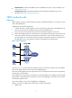
Configuring IPC This chapter provides an overview of Inter-Process Communication (IPC) and describes the IPC monitoring commands. IPC can be configured only at the CLI. Overview IPC provides a reliable communication mechanism among processing units, typically CPUs. This section describes the basic IPC concepts. Node An IPC node is an independent IPC-capable processing unit, typically, a CPU. One LB module is one IPC node, because it has only one CPU.
C ha nn el 2 Figure 41 Relationship between a node, link and channel Link Packet sending modes IPC uses one of the following modes to send packets for upper layer application modules: • Unicast—One node sends packets to another node. • Multicast—One node sends packets to several other nodes. This mode includes broadcast, a special multicast. To use multicast mode, an application module must create a multicast group that includes a set of nodes.
Displaying and maintaining IPC Task Command Remarks Display IPC node information. display ipc node [ | { begin | exclude | include } regular-expression ] Available in any view. Display channel information for a node. display ipc channel { node node-id | self-node } [ | { begin | exclude | include } regular-expression ] Available in any view. Display queue information for a node.
Configuring track The term "router" in this document refers to both routers and LB modules. Track can be configured only at the CLI. Track overview The track module works between application and detection modules, as shown in Figure 42. It shields the differences between various detection modules from application modules. Collaboration is enabled after you associate the track module with a detection module and an application module.
The following detection modules can be associated with the track module: • NQA. • Interface management module. Collaboration between the track module and an application module After being associated with an application module, when the status of the track entry changes, the track module notifies the application module, which then takes proper actions. The following application modules can be associated with the track module: • VRRP. • Static routing. • Policy-based routing. • Interface backup.
Task Remarks Associating the track module with a detection module Associating track with NQA Required. Associating track with interface management Use either approach. Associating track with VRRP Associating the track module with an application module Required. Associating track with static routing Use one of the approaches.
Associating track with interface management The interface management module monitors the physical status or network-layer protocol status of the interface. The interface management module functions as follows when it is associated with a track entry: • When the physical or network-layer protocol status of the interface changes to up, the interface management module informs the track module of the change and the track module sets the track entry to Positive.
• Change the priority of a router according to the status of the uplink. If a fault occurs on the uplink of the router, the VRRP group cannot be aware of the uplink failure. If the router is the master, hosts in the LAN cannot access the external network. This problem can be solved by establishing a track-VRRP group association. Use the detection modules to monitor the status of the uplink of the router and establish collaborations between the detection modules, track module and VRRP.
Step Command Remarks 2. Enter interface view. interface interface-type interface-number N/A 3. Create a VRRP group and configure its virtual IP address. vrrp vrid virtual-router-id virtual-ip virtual-address No VRRP group is created by default. • Associate a track entry with the VRRP VF: vrrp [ ipv6 ] vrid virtual-router-id weight track track-entry-number [ reduced weight-reduced ] 4. Associate track with VRRP VF.
For more information about static route configuration, see Network Management Configuration Guide. To associate track with static routing: Step 1. Enter system view. Command Remarks system-view N/A • Approach 1: 2. Associate the static route with a track entry to check the accessibility of the next hop.
Configuration prerequisites Before you associate track with PBR, create a policy or a policy node and configure the match criteria as well. Configuration procedure You can associate a nonexistent track entry with PBR. The association takes effect only after you use the track command to create the track entry. For more information about PBR, see Network Management Configuration Guide. To associate track with PBR: Step Command Remarks 1. Enter system view. system-view N/A 2.
Associate a standby interface with a track entry so that the standby interface can detect the status of the active interface by checking the status of the track entry, and change its status. • The Positive state of the track entry shows that the link where the active interface resides works normally, and the standby interfaces stay in backup state.
• When LB A works properly, packets from Host A to Host B are forwarded through LB A. When NQA detects that a fault is on the uplink of LB A, packets from Host A to Host B are forwarded through LB B. Figure 43 Network diagram Configuration procedure 1. Configure the IP address of each interface as shown in Figure 43. (Details not shown.) 2. Configure an NQA test group on LB A: # Create an NQA test group with the administrator name admin and the operation tag test.
# Set the priority of LB A in VRRP group 1 to 110. [LBA-GigabitEthernet0/1] vrrp vrid 1 priority 110 # Set the authentication mode of VRRP group 1 to simple, and the authentication key to hello. [LBA-GigabitEthernet0/1] vrrp vrid 1 authentication-mode simple hello # Configure the master to send VRRP packets at an interval of five seconds. [LBA-GigabitEthernet0/1] vrrp vrid 1 timer advertise 5 # Configure LB A to operate in preemptive mode, and set the preemption delay to five seconds.
Run Method : Virtual MAC Total number of virtual routers : 1 Interface GigabitEthernet0/1 VRID : 1 Adver Timer : 5 Admin Status : Up State : Backup Config Pri : 100 Running Pri : 100 Preempt Mode : Yes Delay Time : 5 Become Master : 2200ms left Auth Type : Simple Key : hello Virtual IP : 10.1.1.10 Master IP : 10.1.1.1 The output shows that in VRRP group 1, LB A is the master and LB B is a backup. Packets from Host A to Host B are forwarded through LB A.
Master IP : 10.1.1.2 The output shows that when a fault is on the link between LB A and Router A, the priority of LB A decreases to 80. LB A becomes the backup, and LB B becomes the master. Packets from Host A to Host B are forwarded through LB B. Static routing-track-NQA collaboration configuration example Network requirements As shown in Figure 44, LB A, LB B, Router A, and Router B are connected to two segments 20.1.1.0/24 and 30.1.1.0/24.
Configuration procedure 1. Configure the IP address of each interface as shown in Figure 44. (Details not shown.) 2. Configure LB A: # Configure a static route to 30.1.1.0/24, with the address of the next hop as 10.1.1.2 and the default priority 60. This static route is associated with track entry 1. system-view [LBA] ip route-static 30.1.1.0 24 10.1.1.2 track 1 # Configure a static route to 30.1.1.0/24, with the address of the next hop as 10.3.1.3 and the priority 80. [LBA] ip route-static 30.1.
5. Configure LB B: # Configure a static route to 20.1.1.0/24, with the address of the next hop as 10.2.1.2 and the default priority 60. This static route is associated with track entry 1. system-view [LBB] ip route-static 20.1.1.0 24 10.2.1.2 track 1 # Configure a static route to 20.1.1.0/24, with the address of the next hop as 10.4.1.3 and the default priority 80. [LBB] ip route-static 20.1.1.0 24 10.4.1.3 preference 80 # Configure a static route to 10.1.1.
10.1.1.0/24 Direct 0 0 10.1.1.1 GE0/1 10.1.1.1/32 Direct 0 0 127.0.0.1 InLoop0 10.2.1.0/24 Static 60 0 10.1.1.2 GE0/1 10.3.1.0/24 Direct 0 0 10.3.1.1 GE0/2 10.3.1.1/32 Direct 0 0 127.0.0.1 InLoop0 20.1.1.0/24 Direct 0 0 20.1.1.1 GE0/3 20.1.1.1/32 Direct 0 0 127.0.0.1 InLoop0 30.1.1.0/24 Static 60 0 10.1.1.2 GE0/1 127.0.0.0/8 Direct 0 0 127.0.0.1 InLoop0 127.0.0.1/32 Direct 0 0 127.0.0.
# When the master route fails, the hosts in 20.1.1.0/24 can still communicate with the hosts in 30.1.1.0/24. [LBA] ping -a 20.1.1.1 30.1.1.1 PING 30.1.1.1: 56 data bytes, press CTRL_C to break Reply from 30.1.1.1: bytes=56 Sequence=1 ttl=254 time=2 ms Reply from 30.1.1.1: bytes=56 Sequence=2 ttl=254 time=1 ms Reply from 30.1.1.1: bytes=56 Sequence=3 ttl=254 time=1 ms Reply from 30.1.1.1: bytes=56 Sequence=4 ttl=254 time=2 ms Reply from 30.1.1.1: bytes=56 Sequence=5 ttl=254 time=1 ms --- 30.1.1.
Figure 45 Network diagram Configuration procedure 1. Configure the IP address of each interface as shown in Figure 45. (Details not shown.) 2. Configure a track entry on LB A: # Configure track entry 1, and associate it with the physical status of the uplink interface GigabitEthernet 0/2. [LBA] track 1 interface gigabitethernet 0/2 3. Configure VRRP on LB A: # Create VRRP group 1, and configure the virtual IP address 10.1.1.10 for the group.
VRID : 1 Adver Timer : 1 Admin Status : Up State : Master Config Pri : 110 Running Pri : 110 Preempt Mode : Yes Delay Time : 0 Auth Type : None Virtual IP : 10.1.1.10 Virtual MAC : 0000-5e00-0101 Master IP : 10.1.1.1 VRRP Track Information: Track Object : 1 State : Positive Pri Reduced : 30 # Display detailed information about VRRP group 1 on LB B.
VRRP Track Information: Track Object : 1 State : Negative Pri Reduced : 30 # After shutting down the uplink interface on LB A, display detailed information about VRRP group 1 on LB B.
Configuring NQA NQA can be configured only at the CLI. Overview Network quality analyzer (NQA) allows you to monitor link status, measure network performance, verify the service levels for IP services and applications, and troubleshoot network problems.
Figure 47 Collaboration The following describes how a static route destined for 192.168.0.88 is monitored through collaboration: 1. NQA monitors the reachability to 192.168.0.88. 2. When 192.168.0.88 becomes unreachable, NQA notifies the track module of the change. 3. The track module notifies the static routing module of the state change. 4. The static routing module sets the static route as invalid according to a predefined action. For more information about collaboration, see "Configuring track.
NQA configuration task list Complete the following task to configure the NQA server: Task Remarks Configuring the NQA server Required for NQA operations types of TCP, UDP echo, UDP jitter, and voice. Complete these tasks to configure the NQA client: Task Remarks Enabling the NQA client Required. Configuring an ICMP echo operation Configuring a DHCP operation Configuring a DNS operation Configuring an FTP operation Configuring an HTTP operation Required.
Step Command Remarks 1. Enter system view. system-view N/A 2. Enable the NQA server. nqa server enable Disabled by default. • Approach 1: 3. Configure a listening service. nqa server tcp-connect ip-address port-number • Approach 2: Use at least one approach. nqa server udp-echo ip-address port-number Configuring the NQA client Enabling the NQA client Step Command Remarks N/A 1. Enter system view. system-view 2. Enable the NQA client. nqa agent enable Optional. Enabled by default.
Step 6. Command Configure the string to be filled in the payload of each ICMP echo request. Remarks Optional. data-fill string By default, the string is the hexadecimal number 00010203040506070809. Optional. 7. Specify the VPN where the operation is performed. vpn-instance vpn-instance-name By default, the operation is performed on the public network. This command is available only for the ICMP echo operation. Optional. • Approach 1: 8.
Step Command Specify an interface to perform the DHCP operation. 4. operation interface interface-type interface-number Remarks By default, no interface is specified to perform a DHCP operation. The specified interface must be up. Otherwise, no probe packets can be sent out. Configuring a DNS operation A DNS operation measures the time the NQA client uses to translate a domain name into an IP address through a DNS server.
Step Command Remarks 1. Enter system view. system-view N/A 2. Create an NQA operation and enter NQA operation view. nqa entry admin-name operation-tag By default, no NQA operation is created. 3. Specify the FTP type and enter its view. type ftp N/A 4. Specify the IP address of the FTP server as the destination address of FTP request packets. destination ip ip-address By default, no destination IP address is configured. 5. Configure the source IP address of FTP request packets.
Step Command Remarks 3. Specify the HTTP type and enter its view. type http N/A 4. Configure the IP address of the HTTP server as the destination address of HTTP request packets. destination ip ip-address By default, no destination IP address is configured. Optional. 5. Configure the source IP address of request packets. By default, no source IP address is specified. source ip ip-address The source IP address must be the IP address of a local interface. The local interface must be up.
Step Command Remarks 1. Enter system view. system-view N/A 2. Create an NQA operation and enter NQA operation view. nqa entry admin-name operation-tag By default, no NQA operation is created. 3. Specify the UDP jitter type and enter its view. type udp-jitter N/A 4. Configure the destination address of UDP packets. By default, no destination IP address is configured. destination ip ip-address By default, no destination port number is configured. 5.
NOTE: The display nqa history command does not show the results of the UDP jitter operation. Use the display nqa result command to display the results, or use the display nqa statistics command to display the statistics of the operation. Configuring an SNMP operation An SNMP operation measures the time the NQA client uses to get a value from an SNMP agent. To configure an SNMP operation: Step Command Remarks 1. Enter system view. system-view N/A 2.
Step 3. 4. 5. Specify the TCP type and enter its view. Configure the destination address of TCP packets. Configure the destination port of TCP packets. Command Remarks type tcp N/A By default, no destination IP address is configured. destination ip ip-address The destination address must be the same as the IP address of the listening service configured on the NQA server. By default, no destination port number is configured.
Step Command By default, no destination port number is configured. 5. Configure the destination port of UDP packets. destination port port-number 6. Configure Payload size in each UDP packet. data-size size 7. 8. Remarks The destination port number must be the same as that of the listening service on the NQA server. Optional. 100 bytes by default. Optional. Configure the string to be filled in the payload of each UDP packet. data-fill string Specify the source port of UDP packets.
The evaluation of voice quality depends on users' tolerance for voice quality, which you should consider. For users with higher tolerance for voice quality, use the advantage-factor command to configure the advantage factor. When the system calculates the ICPIF value, it subtracts the advantage factor to modify ICPIF and MOS values, so both objective and subjective factors are considered. The voice operation requires both the NQA server and the NQA client.
Step Command Remarks Optional. 10. Configure Payload size in each voice packet. data-size size By default, the voice packet size depends on the codec type. The default packet size is 172 bytes for G.711A-law and G.711 μ-law codec type, and 32 bytes for G.729 A-law codec type. Optional. 11. Configure the string to be filled in the payload of each voice packet. data-fill string By default, the string is the hexadecimal number 00010203040506070809. 12.
Step Command Remarks Optional. Configure the source IP address of probe packets. 5. By default, no source IP address is specified. The source IP address must be the IP address of a local interface. The local interface must be up. Otherwise, no probe packets can be sent out. source ip ip-address Configuring optional parameters for an NQA operation The following describes how different NQA operation types operate: • A TCP or DLSw operation sets up a connection.
Step Command Remarks Optional. 7. Specify the probe timeout time. probe timeout timeout By default, the timeout time is 3000 milliseconds. This setting is not available for the UDP jitter or voice operation. Optional. 8. 9. Specify the TTL for probe packets. Specify the ToS value in the IP packet header of probe packets. 20 by default. ttl value This setting is not available for the DHCP operation. Optional. 0 by default. tos value This setting is not available for the DHCP operation.
Configuring threshold monitoring Introduction 1. Threshold types An NQA operation supports the following threshold types: { { { average—If the average value for the monitored performance metric either exceeds the upper threshold or goes below the lower threshold, a threshold violation occurs. accumulate—If the total number of times that the monitored performance metric is out of the specified value range reaches or exceeds the specified threshold, a threshold violation occurs.
Step 2. 3. Command Remarks Create an NQA operation and enter NQA operation view. nqa entry admin-name operation-tag By default, no NQA operation is created. Specify an NQA operation type and enter its view.
Step Command Remarks • Enable sending traps to the NMS when specified conditions are met: reaction trap { probe-failure consecutive-probe-failures | test-complete | test-failure cumulate-probe-failures } • Configure a reaction entry for monitoring the duration of an NQA operation (not supported in UDP jitter and voice operations): reaction item-number checked-element probe-duration threshold-type { accumulate accumulate-occurrences | average | consecutive consecutive-occurrences } threshold-value upper
Configuring the NQA statistics function NQA collects statistics for an operation in a statistics group. To view information about the statistics groups, use the display nqa statistics command. To set the interval for collecting statistics, use the statistics interval command. If a new statistics group is to be saved when the number of statistics groups reaches the upper limit, the oldest statistics group is deleted.
To configure the history records saving function: Step Command Remarks 1. Enter system view. system-view N/A 2. Create an NQA operation and enter NQA operation view. nqa entry admin-name operation-tag By default, no NQA operation is created. 3. Enter NQA operation type view. type { dhcp | dlsw | dns | ftp | http | icmp-echo | snmp | tcp | udp-echo | udp-jitter | voice } N/A 4. Enable saving history records for the NQA operation.
Displaying and maintaining NQA Task Command Remarks Display history records of NQA operations. display nqa history [ admin-name operation-tag ] [ | { begin | exclude | include } regular-expression ] Available in any view. Display the current monitoring results of reaction entries. display nqa reaction counters [ admin-name operation-tag [ item-number ] ] [ | { begin | exclude | include } regular-expression ] Available in any view. Display the result of the specified NQA operation.
Configuration procedure # Assign each interface an IP address. (Details not shown.) # Configure static routes or a routing protocol to make sure the devices can reach each other. (Details not shown.) # Create an ICMP echo operation, and specify 10.2.2.2 as the destination IP address. system-view [LB] nqa entry admin test1 [LB-nqa-admin-test1] type icmp-echo [LB-nqa-admin-test1-icmp-echo] destination ip 10.2.2.2 # Configure 10.1.1.2 as the next hop.
Index Response Status Time 370 3 Succeeded 2012-08-23 15:00:01.2 369 3 Succeeded 2012-08-23 15:00:01.2 368 3 Succeeded 2012-08-23 15:00:01.2 367 5 Succeeded 2012-08-23 15:00:01.2 366 3 Succeeded 2012-08-23 15:00:01.2 365 3 Succeeded 2012-08-23 15:00:01.2 364 3 Succeeded 2012-08-23 15:00:01.1 363 2 Succeeded 2012-08-23 15:00:01.1 362 3 Succeeded 2012-08-23 15:00:01.1 361 2 Succeeded 2012-08-23 15:00:01.
Last succeeded probe time: 2012-11-22 09:54:03.8 Extended results: Packet loss in test: 0% Failures due to timeout: 0 Failures due to disconnect: 0 Failures due to no connection: 0 Failures due to sequence error: 0 Failures due to internal error: 0 Failures due to other errors: 0 Packet(s) arrived late: 0 # Display the history records of the DHCP operation.
[LB] nqa schedule admin test1 start-time now lifetime forever # Stop the DNS operation after a period of time. [LB] undo nqa schedule admin test1 # Display the results of the DNS operation. [LB] display nqa result admin test1 NQA entry (admin admin, tag test1) test results: Destination IP address: 10.2.2.2 Send operation times: 1 Receive response times: 1 Min/Max/Average round trip time: 62/62/62 Square-Sum of round trip time: 3844 Last succeeded probe time: 2012-11-10 10:49:37.
[LB] nqa entry admin test1 [LB-nqa-admin-test1] type ftp # Specify the IP address of the FTP server 10.2.2.2 as the destination IP address. [LB-nqa-admin-test1-ftp] destination ip 10.2.2.2 # Specify 10.1.1.1 as the source IP address. [LB-nqa-admin-test1-ftp] source ip 10.1.1.1 # Set the FTP username to admin, and password to systemtest. [LB-nqa-admin-test1-ftp] username admin [LB-nqa-admin-test1-ftp] password simple systemtest # Configure the device to upload file config.txt to the FTP server.
HTTP operation configuration example Network requirements As shown in Figure 52, configure an HTTP operation on the NQA client to test the time required to obtain data from the HTTP server. Figure 52 Network diagram Configuration procedure # Assign each interface an IP address. (Details not shown.) # Configure static routes or a routing protocol to make sure the devices can reach each other. (Details not shown.) # Create an HTTP operation.
Last succeeded probe time: 2012-11-22 10:12:47.9 Extended results: Packet loss in test: 0% Failures due to timeout: 0 Failures due to disconnect: 0 Failures due to no connection: 0 Failures due to sequence error: 0 Failures due to internal error: 0 Failures due to other errors: Packet(s) arrived late: 0 # Display the history records of the HTTP operation.
[LBA-nqa-admin-test1-udp-jitter] destination port 9000 # Configure the operation to repeat at an interval of 1000 milliseconds. [LBA-nqa-admin-test1-udp-jitter] frequency 1000 [LBA-nqa-admin-test1-udp-jitter] quit # Start the UDP jitter operation. [LBA] nqa schedule admin test1 start-time now lifetime forever # Stop the UDP jitter operation after a period of time. [LBA] undo nqa schedule admin test1 # Display the results of the UDP jitter operation.
# Display the statistics of the UDP jitter operation. [LBA] display nqa statistics admin test1 NQA entry (admin admin, tag test1) test statistics: NO. : 1 Destination IP address: 10.2.2.2 Start time: 2012-05-29 13:56:14.
Figure 54 Network diagram Configuration procedure 1. Assign each interface an IP address. (Details not shown.) 2. Configure static routes or a routing protocol to make sure the devices can reach each other. (Details not shown.) 3. Configure the SNMP agent (Device): # Enable the SNMP agent, and set the SNMP version to all, the read community to public, and the write community to private.
Failures due to internal error: 0 Failures due to other errors: 0 Packet(s) arrived late: 0 # Display the history records of the SNMP operation. [LB] display nqa history admin test1 NQA entry (admin admin, tag test1) history record(s): Index Response Status Time 1 50 Timeout 2012-11-22 10:24:41.1 The output shows that LB uses 50 milliseconds to receive a response from the SNMP agent.
# Stop the TCP operation after a period of time. [LBA] undo nqa schedule admin test1 # Display the results of the TCP operation. [LBA] display nqa result admin test1 NQA entry (admin admin, tag test1) test results: Destination IP address: 10.2.2.2 Send operation times: 1 Receive response times: 1 Min/Max/Average round trip time: 13/13/13 Square-Sum of round trip time: 169 Last succeeded probe time: 2012-11-22 10:27:25.
[LBB] nqa server enable [LBB] nqa server udp-echo 10.2.2.2 8000 4. Configure LB A: # Create a UDP echo operation. system-view [LBA] nqa entry admin test1 [LBA-nqa-admin-test1] type udp-echo # Configure 10.2.2.2 as the destination IP address and port 8000 as the destination port. [LBA-nqa-admin-test1-udp-echo] destination ip 10.2.2.2 [LBA-nqa-admin-test1-udp-echo] destination port 8000 # Enable the saving of history records.
Figure 57 Network diagram Configuration procedure 1. Assign each interface an IP address. (Details not shown.) 2. Configure static routes or a routing protocol to make sure the devices can reach each other. (Details not shown.) 3. Configure LB B: # Enable the NQA server, and configure a listening service to listen on IP address 10.2.2.2 and UDP port 9000. system-view [LBB] nqa server enable [LBB] nqa server udp-echo 10.2.2.2 9000 4. Configure LB A: # Create a voice operation.
Packet(s) arrived late: 0 Voice results: RTT number: 1000 Min positive SD: 1 Min positive DS: 1 Max positive SD: 204 Max positive DS: 1297 Positive SD number: 257 Positive DS number: 259 Positive SD sum: 759 Positive DS sum: 1797 Positive SD average: 2 Positive DS average: 6 Positive SD square sum: 54127 Positive DS square sum: 1691967 Min negative SD: 1 Min negative DS: 1 Max negative SD: 203 Max negative DS: 1297 Negative SD number: 255 Negative DS number: 259 Negative SD sum: 759 Negat
Positive SD number: 1030 Positive DS number: 1024 Positive SD sum: 4363 Positive DS sum: 5423 Positive SD average: 4 Positive DS average: 5 Positive SD square sum: 497725 Positive DS square sum: 2254957 Min negative SD: 1 Min negative DS: 1 Max negative SD: 360 Max negative DS: 1297 Negative SD number: 1028 Negative DS number: 1022 Negative SD sum: 1028 Negative DS sum: 1022 Negative SD average: 4 Negative DS average: 5 Negative SD square sum: 495901 Negative DS square sum: 5419 One way
[LB] nqa schedule admin test1 start-time now lifetime forever # Stop the DLSw operation after a period of time. [LB] undo nqa schedule admin test1 # Display the results of the DLSw operation. [LB] display nqa result admin test1 NQA entry (admin admin, tag test1) test results: Destination IP address: 10.2.2.2 Send operation times: 1 Receive response times: 1 Min/Max/Average round trip time: 19/19/19 Square-Sum of round trip time: 361 Last succeeded probe time: 2012-11-22 10:40:27.
2. On LB, configure a unicast static route, and associate the static route with a track entry: # Configure a static route, and associate the static route with track entry 1. system-view [LB] ip route-static 10.1.1.2 24 10.2.1.1 track 1 3. On LB, configure an ICMP echo operation: # Create an NQA operation with the administrator name being admin and operation tag being test1. [LB] nqa entry admin test1 # Configure the NQA operation type as ICMP echo.
127.0.0.1/32 Direct 0 0 127.0.0.1 InLoop0 The output shows that the static route with the next hop 10.2.1.1 is active, and the status of the track entry is Positive. # Remove the IP address of GigabitEthernet 0/1 on Device A. system-view [DeviceA] interface gigabitethernet 0/1 [DeviceA-GigabitEthernet0/1] undo ip address # On LB, display information about all the track entries.
Configuring interface backup The term "router" in this document refers to both routers and LB modules. Interface backup can be configured only at the CLI. Overview Interface backup increases network reliability. The active interface transmits services, and the standby interfaces are in the backup state. When the active interface fails or the link fails, or when the traffic on the active interface exceeds the configured threshold, a standby interface is activated to transmit services.
Active/standby mode As shown in Figure 61, interface GigabitEthernet 0/2 on Router A acts as the active interface and interfaces GigabitEthernet 0/1 and GigabitEthernet 0/3 act as the standby interfaces. Figure 61 Diagram for active/standby mode In active/standby mode, only one interface transmits data at any given time. • When the active interface is operating properly, even if the traffic is overloaded, the standby interface is in a backup state. All traffic is transmitted by the active interface.
Interface backup configuration task list Task Remarks Configuring active/standby mode Configuring interface backup Associating an interface with a track entry Optional Configuring load balancing Optional Configuring the delay timer for the backup function to take effect on system startup Optional Configuring interface backup You can configure interface backup through active/standby mode or association between an interface and a track entry, but you cannot configure them at the same time.
Associating an interface with a track entry You can associate a standby interface with a track entry to enable the interface to monitor the state of the active interface through the track entry and change the backup state of the interface accordingly. • If the state of the track entry is positive, the link connecting the active interface is normal and the standby interface stays in the backup state.
Step Command Remarks No load balancing thresholds are configured by default. 4. Configure load balancing thresholds. standby threshold enable-threshold disable-threshold 5. Configure the interval for detecting traffic size on the active interface. standby timer flow-check interval Optional. 30 seconds by default. Configuring the delay timer for the backup function to take effect on system startup Generally, HP recommends using the default settings.
Interface backup configuration examples Multi-interface backup configuration example Network requirements Use interfaces GigabitEthernet 0/1 and GigabitEthernet 0/3 on LB to back up the active interface GigabitEthernet 0/2, assigning interface GigabitEthernet 0/1 a higher priority, and configure switchover delays. Figure 63 Network diagram Configuration procedure 1. Configure IP addresses: Follow Figure 63 to configure the IP address and subnet mask for each interface. (Details not shown.) 2.
4. Verify the configuration on LB: # Display the state of the active and standby interfaces. [LB-GigabitEthernet0/2] display standby state Interface Interfacestate Standbystate Standbyflag Pri Loadstate GigabitEthernet0/2 UP MUP MU GigabitEthernet0/1 STANDBY STANDBY BU 30 GigabitEthernet0/3 STANDBY STANDBY BU 20 Backup-flag meaning: M---MAIN B---BACKUP D---LOAD P---PULLED V---MOVED U---USED # Manually shut down the active interface GigabitEthernet 0/2.
Configuration procedure 1. Configure IP addresses: Follow Figure 64 to configure the IP address and subnet mask for each interface. (Details not shown.) 2. Configure a static route: # On LB, configure a static route to the segment 192.168.2.0/24 where Host B resides. system-view [LB] ip route-static 192.168.2.0 24 gigabitethernet0/1 1.1.1.2 [LB] ip route-static 192.168.2.0 24 gigabitethernet0/2 2.2.2.2 [LB] ip route-static 192.168.2.0 24 gigabitethernet0/3 3.3.3.
# When the data traffic on the active interface GigabitEthernet 0/2 exceeds 8000 kbps (that is, 10000 kbps × 80%), standby interface GigabitEthernet 0/1 with a higher priority is enabled first. Then you can view the state of the active and standby interfaces.
Support and other resources Contacting HP For worldwide technical support information, see the HP support website: http://www.hp.
Conventions This section describes the conventions used in this documentation set. Command conventions Convention Description Boldface Bold text represents commands and keywords that you enter literally as shown. Italic Italic text represents arguments that you replace with actual values. [] Square brackets enclose syntax choices (keywords or arguments) that are optional. { x | y | ... } Braces enclose a set of required syntax choices separated by vertical bars, from which you select one.
Network topology icons Represents a generic network device, such as a router, switch, or firewall. Represents a routing-capable device, such as a router or Layer 3 switch. Represents a generic switch, such as a Layer 2 or Layer 3 switch, or a router that supports Layer 2 forwarding and other Layer 2 features. Represents a security product, such as a firewall, a UTM, or a load-balancing or security card that is installed in a device.
Index ACDEHINORSTV A H Associating the track module with a detection module,91 High availability technologies,2 I Associating the track module with an application module,92 Interface backup configuration examples,155 Interface backup configuration task list,152 Availability evaluation,1 IPv4 VRRP configuration examples,32 Availability requirements,1 IPv6 VRRP configuration examples,56 C N Configuration guidelines,84 NQA configuration examples,130 Configuring interface backup,152 Configuring IP