
F3215-HP Load Balancing Module High Availability Configuration Guide-6PW101


98
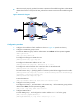
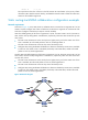
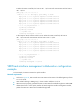
• When LB A works properly, packets from Host A to Host B are forwarded through LB A. When NQA
detects that a fault is on the uplink of LB A, packets from Host A to Host B are forwarded through LB
B.
Figure 43 Network diagram
Configuration procedure
1. Configure the IP address of each interface as shown in Figure 43. (Details not shown.)
2. Configure an NQA test group on LB A:
# Create an NQA test group with the administrator name admin and the operation tag test.
<LBA> system-view
[LBA] nqa entry admin test
# Configure the test type as ICMP echo test.
[LBA-nqa-admin-test] type icmp-echo
# Configure the destination address as 10.1.2.2.
[LBA-nqa-admin-test-icmp-echo] destination ip 10.1.2.2
# Configure the interval between two consecutive tests as 100 milliseconds.
[LBA-nqa-admin-test-icmp-echo] frequency 100
# Create reaction entry 1, specifying that five consecutive probe failures trigger the track module.
[LBA-nqa-admin-test-icmp-echo] reaction 1 checked-element probe-fail threshold-type
consecutive 5 action-type trigger-only
[LBA-nqa-admin-test-icmp-echo] quit
# Start the NQA test.
[LBA] nqa schedule admin test start-time now lifetime forever
3. Configure a track entry on LB A:
# Configure track entry 1, and associate it with reaction entry 1 of the NQA test group (with the
administrator admin, and the operation tag test).
[LBA] track 1 nqa entry admin test reaction 1
4. Configure VRRP on LB A:
# Create VRRP group 1, and configure the virtual IP address 10.1.1.10 for the group.
[LBA] interface gigabitethernet0/1
[LBA-GigabitEthernet0/1] vrrp vrid 1 virtual-ip 10.1.1.10