
F3215-HP Load Balancing Module High Availability Configuration Guide-6PW101

144
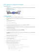
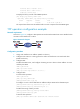
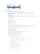
Figure 57 Network diagram
Configuration procedure
1. Assign each interface an IP address. (Details not shown.)
2. Configure static routes or a routing protocol to make sure the devices can reach each other.
(Details not shown.)
3. Configure LB B:
# Enable the NQA server, and configure a listening service to listen on IP address 10.2.2.2 and
UDP port 9000.
<LBB> system-view
[LBB] nqa server enable
[LBB] nqa server udp-echo 10.2.2.2 9000
4. Configure LB A:
# Create a voice operation.
<LBA> system-view
[LBA] nqa entry admin test1
[LBA-nqa-admin-test1] type voice
# Configure 10.2.2.2 as the destination IP address and port 9000 as the destination port.
[LBA-nqa-admin-test1-voice] destination ip 10.2.2.2
[LBA-nqa-admin-test1-voice] destination port 9000
[LBA-nqa-admin-test1-voice] quit
# Start the voice operation.
[LBA] nqa schedule admin test1 start-time now lifetime forever
# Stop the voice operation after a period of time.
[LBA] undo nqa schedule admin test1
# Display the results of the voice operation.
[LBA] display nqa result admin test1
NQA entry (admin admin, tag test1) test results:
Destination IP address: 10.2.2.2
Send operation times: 1000 Receive response times: 1000
Min/Max/Average round trip time: 31/1328/33
Square-Sum of round trip time: 2844813
Last succeeded probe time: 2012-06-13 09:49:31.1
Extended results:
Packet loss in test: 0%
Failures due to timeout: 0
Failures due to disconnect: 0
Failures due to no connection: 0
Failures due to sequence error: 0
Failures due to internal error: 0
Failures due to other errors: 0