
F3215-HP Load Balancing Module High Availability Configuration Guide-6PW101

150
Configuring interface backup
The term "router" in this document refers to both routers and LB modules.
Interface backup can be configured only at the CLI.
Overview
Interface backup increases network reliability. The active interface transmits services, and the standby
interfaces are in the backup state. When the active interface fails or the link fails, or when the traffic on
the active interface exceeds the configured threshold, a standby interface is activated to transmit
services.
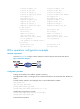
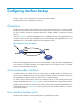
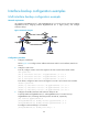
As shown in Figure 60, in
terfaces GigabitEthernet 0/1, GigabitEthernet 0/2, and GigabitEthernet 0/3
on Router A back up each other. GigabitEthernet 0/2 transmits data, and GigabitEthernet 0/1 and
GigabitEthernet 0/3 are standby interfaces that have different priorities.
Figure 60 Diagram for interface backup
When interface GigabitEthernet 0/2 or its link to Router B fails, or when the traffic on GigabitEthernet
0/2 exceeds the configured threshold, the standby interface with the highest priority is activated,
ensuring uninterrupted data transmission.
Active and standby interfaces
In interface backup, an interface can be an active interface or standby interface. Interfaces that can
serve as active or standby interfaces are Layer 3 Ethernet interfaces and Layer 3 Ethernet subinterfaces.
Ten-GigabitEthernet interfaces cannot be used as active or standby interfaces.
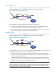
An active interface transmits data, and can be configured with up to three standby interfaces (for
example, GigabitEthernet 0/2 in Figure 60)
. Up to 10 active interfaces can be configured on a device.
Standby interfaces function as backups for active interfaces (for example, interfaces GigabitEthernet 0/1
and GigabitEthernet 0/3 in Figure 60)
, which are generally idle. One standby interface can only back
up one active interface.
How interface backup works
Interface backup operates in active/standby mode or in load balancing mode.