
F3215-HP Load Balancing Module High Availability Configuration Guide-6PW101

151
Active/standby mode
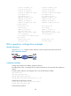
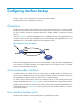
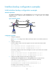
As shown in Figure 61, interface GigabitEthernet 0/2 on Router A acts as the active interface and
interfaces GigabitEthernet 0/1 and GigabitEthernet 0/3 act as the standby interfaces.
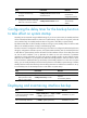
Figure 61 Diagram for active/standby mode
In active/standby mode, only one interface transmits data at any given time.
• When the active interface is operating properly, even if the traffic is overloaded, the standby
interface is in a backup state. All traffic is transmitted by the active interface.
• If the active interface fails, the standby interface with highest priority takes over to transmit data.
• When the active interface is restored, it resumes data transmission.
Load balancing mode
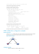
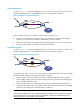
As shown in Figure 62, interface GigabitEthernet 0/2 on Router A acts as the active interface, and
interfaces GigabitEthernet 0/1 and GigabitEthernet 0/3 act as the standby interfaces.
Figure 62 Diagram for load balancing mode
In load balancing mode, you can set an upper threshold (enable-threshold) and a lower threshold
(disable-threshold). Traffic can be shared among multiple interfaces:
• When the traffic on the active interface exceeds the predefined enable-threshold, the highest
priority standby interface is activated. Other standby interfaces are activated in descending priority
order if exceeding traffic still exists.
• When the traffic on the active interface decreases below the predefined disable-threshold, the
system shuts down the lowest priority standby interface first and then shuts down the other standby
interfaces in ascending priority order depending on traffic size.
NOTE:
A
dopt active/standby or load balancin
g
mode dependin
g
on whether you have confi
g
ured an upper or
lower threshold for the active interface traffic. If this threshold is configured, load balancing mode is
adopted. Otherwise, active/standby mode is adopted.