
F3215-HP Load Balancing Module High Availability Configuration Guide-6PW101

155
Interface backup configuration examples
Multi-interface backup configuration example
Network requirements
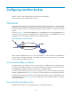
Use interfaces GigabitEthernet 0/1 and GigabitEthernet 0/3 on LB to back up the active interface
GigabitEthernet 0/2, assigning interface GigabitEthernet 0/1 a higher priority, and configure
switchover delays.
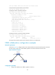
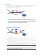
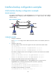
Figure 63 Network diagram
Configuration procedure
1. Configure IP addresses:
Follow Figure 63 to c
onfigure the IP address and subnet mask for each interface. (Details not
shown.)
2. Configure a static route:
# On LB, configure a static route to the segment 192.168.2.0/24 where Host B resides.
<LB> system-view
[LB] ip route-static 192.168.2.0 24 gigabitethernet 0/1 1.1.1.2
[LB] ip route-static 192.168.2.0 24 gigabitethernet 0/2 2.2.2.2
[LB] ip route-static 192.168.2.0 24 gigabitethernet 0/3 3.3.3.2
# On Router, configure a static route to the segment 192.168.1.0/24 where Host A resides.
<Router> system-view
[Router] ip route-static 192.168.1.0 24 gigabitethernet 0/1 1.1.1.1
[Router] ip route-static 192.168.1.0 24 gigabitethernet 0/2 2.2.2.1
[Router] ip route-static 192.168.1.0 24 gigabitethernet 0/3 3.3.3.1
3. Configure the standby interfaces and switchover delays on LB:
# Specify interfaces GigabitEthernet 0/1 and GigabitEthernet 0/3 on LB to back up
GigabitEthernet 0/2, and assign them the priorities 30 and 20, respectively.
[LB] interface gigabitethernet0/2
[LB-GigabitEthernet0/2] standby interface gigabitethernet 0/1 30
[LB-GigabitEthernet0/2] standby interface gigabitethernet 0/3 20
# Configure switchover delays to 10 seconds.
[LB-GigabitEthernet0/2] standby timer delay 10 10