
F3215-HP Load Balancing Module High Availability Configuration Guide-6PW101


156
4. Verify the configuration on LB:
# Display the state of the active and standby interfaces.
[LB-GigabitEthernet0/2] display standby state
Interface Interfacestate Standbystate Standbyflag Pri Loadstate
GigabitEthernet0/2 UP MUP MU
GigabitEthernet0/1 STANDBY STANDBY BU 30
GigabitEthernet0/3 STANDBY STANDBY BU 20
Backup-flag meaning:
M---MAIN B---BACKUP V---MOVED U---USED
D---LOAD P---PULLED
# Manually shut down the active interface GigabitEthernet 0/2.
[LB-GigabitEthernet0/2] shutdown
# 10 seconds after the active interface was shut down, standby interface GigabitEthernet 0/1 with
a higher priority is enabled. Then you can view the state of the active and standby interfaces.
[LB-GigabitEthernet0/2] display standby state
Interface Interfacestate Standbystate Standbyflag Pri Loadstate
GigabitEthernet0/2 DOWN MDOWN MU
GigabitEthernet0/1 UP UP BU 30
GigabitEthernet0/3 STANDBY STANDBY BU 20
Backup-flag meaning:
M---MAIN B---BACKUP V---MOVED U---USED
D---LOAD P---PULLED
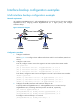
Multi-interface load balancing configuration example
Network requirement
Use interfaces GigabitEthernet 0/1 and GigabitEthernet 0/3 on LB to back up the active interface
GigabitEthernet 0/2, assigning interface GigabitEthernet 0/1 a higher priority.
Configure the available bandwidth used for setting the thresholds and the enable-threshold and
disable-threshold of load balancing.
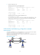
Figure 64 Network diagram