
F3215-HP Load Balancing Module High Availability Configuration Guide-6PW101

47
The output shows that in VRRP group 1 LB A is the master, LB B is the backup and the host with the
default gateway of 202.38.160.111/24 accesses the Internet through LB A. In VRRP group 2 LB
A is the backup, LB B is the master and the host with the default gateway of 202.38.160.112/24
accesses the Internet through LB B.
NOTE:
To implement load balancing between the VRRP groups, be sure to configure the default gateway as
202.38.160.111 or 202.38.160.112 on the hosts on network segment 202.38.160.0/24.
VRRP load balancing mode configuration example
Network requirements
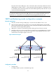
• LB A, LB B, and LB C belong to VRRP group 1 with the virtual IP address of 10.1.1.1/24.
• H o s t s o n n e t w o r k s e g m e n t 10 .1.1. 0 / 24 u s e 10 .1.1.1 / 24 a s t h e i r d e f a u l t g a t e w a y. U s e t h e V R R P
group to make sure that when a gateway (LB A, LB B, or LB C) fails, the hosts on the LAN can access
the external network through another gateway.
• VRRP group 1 operates in load balancing mode to make good use of network resources.
• Configure a track entry on LB A, LB B, and LB C to monitor their own GigabitEthernet 0/2. When
the interface on LB A, LB B, or LB C fails, the weight of the corresponding LB decreases so that
another device with a higher weight can take over.
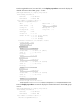
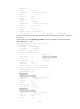
Figure 28 Network diagram
Configuration procedure
1. Configure LB A:
# Configure VRRP to operate in load balancing mode.
Host A Host B Host C
LB A LB B LB C
GE0/1
IP: 10.1.1.2/24
VIP: 10.1.1.1/24
Network
GE0/1
IP: 10.1.1.3/24
VIP: 10.1.1.1/24
GE0/1
IP: 10.1.1.4/24
VIP: 10.1.1.1/24
Master
AVF 1
Backup
AVF 2
Backup
AVF 3
IP: 10.1.1.5/24
Gateway IP: 10.1.1.1/24
IP: 10.1.1.6/24
Gateway IP: 10.1.1.1/24
IP: 10.1.1.7/24
Gateway IP: 10.1.1.1/24
GE0/2
GE0/2
GE0/2