HP Load Balancing Module Load Balancing Configuration Guide Part number: 5998-4218 Software version: Feature 3221 Document version: 6PW100-20130326
Legal and notice information © Copyright 2013 Hewlett-Packard Development Company, L.P. No part of this documentation may be reproduced or transmitted in any form or by any means without prior written consent of Hewlett-Packard Development Company, L.P. The information contained herein is subject to change without notice.
Contents Configuring load balancing ········································································································································ 1 Working mechanism of server load balancing ············································································································· 1 NAT-mode Layer 4 server load balancing ············································································································ 2 DR-mode Layer 4 server load bala
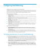
Configuring load balancing Load balancing can be configured only in the Web interface. Load balancing (referred to as LB hereinafter) is a cluster technology to distribute specific services such as network services and network traffic among multiple network devices (for example servers and firewalls) , enhancing service processing capability and ensuring high availability of services.
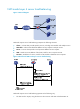
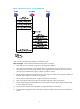
NAT-mode Layer 4 server load balancing Figure 1 Network diagram NAT-mode Layer 4 server load balancing comprises the following elements: • Cluster—A cluster that provides specific services, including an LB module and multiple servers. • LB module—A device that distributes different service requests to multiple servers. • Server—A server that responds to and processes different service requests. • VSIP—Virtual Service IP address of the cluster, used for users to request services.
2. Upon receiving the request, the LB module uses an algorithm to calculate to which server it distributes the request. 3. The LB module uses the Destination NAT (DNAT) technology to distribute the request, using the host IP as the source IP and Server IP as the destination IP. 4. The server receives and processes the request and then sends a response, using the server IP as the source IP, and the host IP as the destination IP. 5.
Figure 4 Work flow of DR-mode Layer 4 server load balancing DR-mode Layer 4 server load balancing operates in the following way: 1. The host sends a request, using VSIP as the destination address. 2. Upon receiving the request, the general device forwards it to LB module. The VSIP cannot be contained in an ARP request and response, so the general device only forwards the request to the LB module. 3.
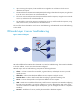
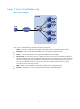
Layer 7 server load balancing Figure 5 Network diagram Layer 7 server load balancing comprises the following elements: • Cluster—A cluster consists of an LB module and multiple servers to provide specific services. • LB module—A device that distributes different service requests to multiple servers. • Server—A server that responds to and processes different service requests. • Server group—A real service group is a logical concept.
Figure 6 Work flow of Layer 7 server load balancing Layer 7 server load balancing operates in the following way: Step 1 through 3—Host and the LB module establish a TCP connection. 4. Host sends a service request, using VSIP as the destination address. 5.
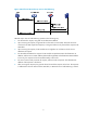
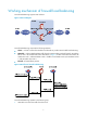
Working mechanism of firewall load balancing Firewall load balancing supports IPv4 and IPv6. Figure 7 Network diagram Firewall load balancing comprises the following elements: • Cluster—A cluster consists of LB modules and firewalls to provide network traffic load balancing. • LB module—A device that distributes traffic from the request sender to multiple firewalls. LB modules fall into level 1 LB modules and level 2 LB modules.
2. LB module A forwards the traffic to a firewall based on the destination IP address range and the pre-configured load balancing rules of the traffic. 3. The firewall forwards the traffic to LB module B. 4. As a level 2 LB module, LB module B records the firewall that forwards the traffic and then forwards the traffic to the destination. 5. LB module B receives the traffic sent from the destination. 6. LB module B forwards the traffic to the firewall recorded in step 4. 7.
Figure 10 Relationship between the components of the server load balancing module • Real service group—A group of real services. • Real services—Entities that process services in a cluster (such as servers in Figure 1, and Figure 3, and firewalls Figure 7. A real service group comprises multiple real services. • Virtual service—A logical entity that faces users. For Layer 4 server load balancing and firewall load balancing, a virtual service corresponds to one real service group.
Step Remarks 2. Unidirectional traffic detection must be enabled on an LB module in DR server load balancing. This task is optional in other cases. Enabling unidirectional traffic detection To configure unidirectional traffic detection, navigate to Security > Session Table > Configuration. 3. Configuring a health monitoring method A health monitoring method must be configured if you adopt SSL health monitoring. This task is optional in other cases. 4. Creating a real service group Required. 5.
Configuring a health monitoring method Load balancing supports multiple health monitoring types. This section describes only the types supported by IPv4 server load balancing. • ARP—Monitors the availability of a server through ARP. • DNS—Monitors the availability of a DNS server through DNS. • FTP—Monitors the availability of an FTP server through FTP. • HTTP—Monitors the availability of an HTTP service through HTTP access. • ICMP—Monitors the reachability of a server by sending ICMP messages.
Figure 12 Health monitoring 2. Click Add. The page for adding a health monitoring method appears. Figure 13 Adding a health monitoring method 3. Configure the parameters as described in Table 1. 4. Click Apply.
Table 1 Configuration items Item Description Name Health monitoring method name. Health Monitoring Health monitoring type. Check Interval Interval at which health monitoring is performed. Timeout Timeout for a health monitoring operation. Retry Times When the number of retry times is n, if health monitoring is performed for n times and the corresponding server or port is unavailable, the health monitoring is considered failed.
Item Description Username Username and password for logging in to the RADIUS server in RADIUS health monitoring, case sensitive. Password Authentication Server Shared Key RADIUS Packet Source IP Protocol Allowed Status Code The default username is admin, and there is no password. Shared key for RADIUS authentication packets in RADIUS health monitoring. The default authentication server shared key is 0123456789. Source IP address of RADIUS packets in RADIUS health monitoring.
Item Description Local certificate of an SSL client policy in SSL health monitoring, used for an SSL server to perform certificate-based authentication on the client. Client Certificate To apply a certificate, select Security > Certificate Management > Certificate. IMPORTANT: If you adopt SSL health monitoring, you must configure the Client Certificate.
If you click the Number of Real Services link for a real service group, the Real Service tab appears, displaying information about the real services that belong to the real service group. 2. Click Add. The real service group configuration page appears. Figure 15 Adding a real service group 3. Configure the parameters as described in Table 2. 4. Click Apply.
Item Description Select an algorithm that a real service group uses to distribute services and traffic: • Round Robin—Assigns new connections to each real service in turn. • Weighted Round Robin—Assigns new connections to real services based on the weights of real services. A higher weight indicates more new connections will be assigned. • Least Connections—New connections are always assigned to the real service with the fewest number of active connections.
Item Description Specify the health monitoring success criteria. Health Monitoring Success Criteria • If you select All, health monitoring succeeds only when all the selected health monitoring methods succeed. • If you select At Least and specify a value, health monitoring succeeds when the number of succeeded health monitoring methods reaches the specified value.
Item Description Identification of a real service group in Layer 7 server load balancing, that is, the common characteristics of all the real services in the real service group. The character configuration depends on the real service group method specified in the virtual service. The virtual service selects an appropriate real service group for different packets according to the real service group method and characters of the real services.
Creating a real service 1. Select Load Balance > Server Load Balance > IPv4 from the navigation tree. 2. Click the Real Service tab. The real service page appears. Figure 16 Real service To view the configurations and statistics of a real service, click the Real Service Name link of the real service. When a real service is available, and is neither enabled with slow-offline nor stopping service, its status is displayed as .
Item Description Real Service IP Specify the IP address (IPv4 address) of a server or network device that processes services. Set a port number that is related to the following parameters: • Health monitoring method for a real service group—If this parameter is 0, the port number of the real service is used for heath monitoring (except RADIUS and SIP health monitoring).
• If you enable slow-offline, the real service continues to process the traffic previously assigned to it, but the LB module does not assign any new service to the real service. Remove the server or network device from the cluster after the original services are processed to avoid service interruption. To stop service or enable slow-offline: 1. Select Load Balance > Server Load Balance > IPv4 from the navigation tree. 2. Click Real Service. The real service page appears. 3.
Figure 19 Virtual service To view the configurations and statistics of a real service, click the Real Service Name link of the real service. To view the configuration information of a real service group, click the Real Service Group link of a virtual service. If you click the Number of Real Services link of a real service group, the page will go to the Real Service tab, which displays only information about the real services that belong to the virtual service group. 3. Click Add.
Figure 20 Creating a virtual service for Layer 4 server load balancing 5. Configure the parameters as described in Table 4. 6. Click Apply. Table 4 Configuration items Item Description Virtual Service Name Set a virtual service name, which uniquely identifies a virtual service. LB Layer Select the Four option. VPN Instance Select the VPN instance to which the virtual service belongs. Virtual Service IP Mask Protocol Specify the VSIP of the cluster.
Item Description When you select UDP as the protocol, set whether to enable the mechanism of distributing services based on packets. Enable Forced LB Packet exchange for some UDP-based services, such as DNS, RADIUS, and so on, can be completed in one exchanging process, and in some specific scenarios, the quintuple of packets is the same. In this case, load balancing cannot be implemented on service packets based on the session-based load balancing mode.
Item Description Select a method for associating real services and connections that access the same virtual service. Using a persistence method can reduce times that LB module distributes traffic and services. • If you do not select a persistence method, no real services or connections are associated. • Source IP—Connections that have the same source address will be associated with the same real service.
Figure 21 Creating a virtual service for Layer 7 server load balancing 5. Configure the parameters as described in Table 5. 6. Click Apply. Table 5 Configuration items Item Description Virtual Service Name Set a virtual service name, which uniquely identifies a virtual service. LB Layer Select the Seven option. VPN Instance Select the VPN instance to which the virtual service belongs. Virtual Service IP Specify the VSIP of the cluster.
Item Description When you select UDP as the protocol, set whether to enable the mechanism of distributing services based on packets. Enable Forced LB Packet exchange for some UDP-based services, such as DNS and RADIUS, can be completed in one exchanging process, and in some specific scenarios, the quintuple of packets is the same. In this case, load balancing cannot be implemented on service packets based on the session-based load balancing mode.
Item Description Select a method for associating real services and connections that access the same virtual service. Using a persistence method can reduce the number of times for an LB module to distribute services and traffic. • If you do not select any method, no association is performed. • Cookie Insert—If no Set-Cookie field with server information is carried in a response sent by the server, the LB module adds a Set-Cookie field including server information.
Item Description Cookie Info If you select Cookie Get as the persistence method, set the information in the Cookies users are interested in, such as session-id, session-id-time (the time when a session was established) and user ID. • If you select Cookie Get as the persistence method, select this option to get Check all cookies from all responses. If this field is not selected, Set-Cookie information is gotten only from the first response in one connection.
Item Description Match criteria for packets accessing the same virtual service to match different real service groups. • If you do not select a method, it indicates that only one real service group is referenced in the virtual service, and there is no need to match different packets to different real service groups. • HTTP Content—Matches real service groups according to the contents in the HTTP header.
Item Description Whether to enable adding of client source address information in HTTP headers. After you select HTTP Take Source IP, you must select By X-Forwarded-For Header or By User-Defined Header. Carry Source IP in HTTP Header IMPORTANT: • This configuration is meaningful only when the server provides services based on the client source address. • When you select SIP as the persistence method, do not enable this configuration item. Otherwise, load balancing cannot work properly.
Configuring IPv6 server/firewall load balancing IPv6 firewall load balancing and server load balancing are configured in the same way. This section describes the configuration of server load balancing. Configuration considerations The configuration considerations of IPv6 server load balancing are similar to those of Layer 4 IPv4 server load balancing except that the former does not support ACL. For more information, see "Server load balancing configuration considerations.
Figure 23 Public parameter configuration 2. Set whether to enable the saving last hop information function. Enabling this function makes sure responses can be returned on the original path. This function must be enabled on level 2 LB modules in firewall load balancing. 3. Click Apply. Configuring a health monitoring method Load balancing supports multiple health monitoring types. This section describes only the types supported by IPv6 server load balancing.
Figure 24 Health monitoring 2. Click Add. The page for adding a health monitoring method appears. Figure 25 Adding a health monitoring method 3. Configure the parameters as described in Table 6. 4. Click Apply.
Table 6 Configuration items Item Description Name Health monitoring method name. Health Monitoring Health monitoring type. Check Interval Interval at which health monitoring is performed. Timeout Timeout for a health monitoring operation. Retry Times When the number of retry times is n, if health monitoring is performed for n times and the corresponding server or port is unavailable, the health monitoring is considered failed. URL URL to access in HTTP health monitoring.
If you click the Number of Real Services link of a real service group, the page will go to the Real Service tab, which displays only the information about the real services that belong to the real service group. 2. Click Add. The real service group configuration page appears. Figure 27 Adding a real service group 3. Configure the parameters as described in Table 7. 4. Click Apply.
Item Description Select an algorithm that a real service group uses to distribute services and traffic: • Round Robin—Assigns new connections to each real service in turn. • Weighted Round Robin—Assigns new connections to real services based on the weights of real services. A higher weight indicates more new connections will be assigned. • Least Connections—New connections are always assigned to the real service with the fewest number of active connections.
Item Description Select a method that the real service group uses to handle existing connections when it detects that a real service fails: • Keep Connection—Does not actively terminate the connection with the failed real service. Keeping or terminating the connection depends on the timeout mechanism of the protocol. Real Service Troubleshooting • Disconnection—Actively terminates the connection with the failed real service.
Figure 29 Creating a real service 4. Configure the parameters as described in Table 8. 5. Click Apply. Table 8 Configuration items Item Description Real Service Name Set a real service name, which uniquely identifies a real service. Real Service IP Specify the IP address (IPv6 address) of a server or network device that processes services.
Item Description Health Monitoring Success Criteria When you select Specified for Health Monitoring Method, you must specify the health monitoring success criteria. • If you select All, health monitoring succeeds only when all the selected health monitoring methods succeed. • If you select At Least and specify a value, health monitoring succeeds when the number of succeeded health monitoring methods reaches the specified value.
Creating a virtual service 1. Select Load Balance > Server Load Balance > IPv6 from the navigation tree. 2. Click Virtual Service. The virtual service page appears. Figure 31 Virtual service To view the configurations and statistics of a real service, click the Real Service Name link of the real service. To view the configuration information of a real service group, click the Real Service Group link of a virtual service.
Figure 32 Creating a virtual service 4. Configure the parameters as described in Table 9. 5. Click Apply. Table 9 Configuration items Item Description Virtual Service Name Set a virtual service name, which uniquely identifies a virtual service. VPN Instance Select the VPN instance to which the virtual service belongs. Virtual Service IP Specify the VSIP (IPv6 address) and prefix length of the cluster, or the destination network segment of the packets to be load balanced.
Item Description Configure an SNAT IP address pool. The option can be set when Enable SNAT is selected. Its default value is the virtual service IP address. SNAT IP Pool The start IP address and end IP address must be both configured or both empty, and the end IP address must be greater than the start IP address. IMPORTANT: The SNAT address pool cannot have overlapping address spaces with the address pool configured for dynamic NAT on an interface of the device.
Figure 33 Statistics Load balancing configuration examples Layer 4 IPv4 server load balancing configuration example Network requirements As shown in Figure 34, three servers Server A, Server B, and Server C can provide HTTP services. Server A has the highest hardware configuration, and Server B the second. Enable these three servers to provide HTTP services together, and all HTTP traffic is required to be filtered by the LB module. Cluster provides HTTP service.
Figure 34 Network diagram Cluster Server A 192.168.1.1:8080 LB product Server B IP network 192.168.1.2:8080 VSIP 61.159.4.100 Server C 192.168.1.3:8080 Configuring the LB module Assume that the IP addresses of the interfaces on the LB module and the zone to which they belong have been configured. The following describes the configurations of load balancing in detail. 1. Create real service group HTTPGroup: a. Select Load Balance > Server Load Balance > IPv4 from the navigation tree.
2. Create real service ServerA for Server A: a. Click the Real Service tab. b. Click Add. The Add Real Service page appears. c. Enter the real service name ServerA, IP address 192.168.1.1, port number 8080, and weight 150, and select the real service group HTTPGroup. d. Click Apply. Figure 36 Creating a real service 3. Create real service ServerB for Server B: a. Click Add on the Real Service tab. The Add Real Service page appears. b. Enter the real service name ServerB, IP address 192.168.1.
d. Select Four for LB Layer. e. Click Add next to Virtual Service IP, enter the IP address of the virtual service 61.159.4.100, and click Apply. f. Select the mask 32 (255.255.255.255) and protocol type TCP. g. Enter the port number 80. h. Select the forwarding mode NAT, real service group HTTPGroup, and the Enable Virtual Service option. i. Click Apply.
Figure 38 Statistics Figure 38 shows that the total number of connections of Server A, Server B, and Server C is in a ratio of 15:12:10, which is the same as that of the configured weights. Therefore, the server load balancing function has taken effect. Layer 7 IPv4 server load balancing configuration example Network requirements As shown in Figure 39, four servers Server A, Server B, Server C, and Server D can provide HTTP services.
Figure 39 Network diagram Configuring the LB module Assume that the IP addresses of the interfaces on the LB module and the zone to which they belong have been configured and the corresponding zone is enabled with the virtual fragment reassembly function. The following describes the configurations of load balancing in detail. 1. Create real service group SongsGroup: a. Select Load Balance > Server Load Balance > IPv4 from the navigation tree. The Real Service Group tab appears. b. Click Add.
Figure 40 Creating a real service group 2. Create real service group NewsGroup: a. Click Add on the Real Service page. The Add Real Service Group page appears. b. Enter the real service group name NewsGroup, select the algorithm Round Robin, health monitoring method icmp, and troubleshooting method Keep Connection, and enter character /news. c. 3. Click Apply. Create real service ServerA for Server A: a. Click the Real Service tab, and click Add. The Add Real Service page appears. b.
Figure 41 Creating a real service 4. Create real service ServerB for Server B: a. Click Add on the Real Service tab. The Add Real Service page appears. b. Enter the real service name ServerB, IP address 192.168.1.2, and port number 80, and select the real service group SongsGroup. c. 5. Click Apply. Create real service ServerC for Server C: a. Click Add on the Real Service tab. The Add Real Service page appears. b. Enter the real service name ServerC, IP address 192.168.1.
e. Select URL-Function in HTTP Content as the Real Service Group Method. f. Select SongsGroup and NewsGroup in the Available Groups area, and then click the << button to add them to the selected real service groups. g. Select the Enable Virtual Service option. h. Click Apply. Figure 42 Creating virtual service VS Verifying the configuration Host request songs from the server group.
Figure 43 Statistics (I) 4. Click the icon to clear the statistics of virtual service vs. 5. Host request news from the server group. 6. After the server group runs for a period of time, click Refresh to display the statistics to verify the configuration of load balancing.
Figure 44 Statistics (II) The statistics show that when Host requests songs from the server group, there are connections only on Server A and Server B, and the total number of connections of Server A and Server B is in a ratio of 1:1; when Host requests news from the server group, there are connections only on Server C and Server D, and the total number of connections of Server C and Server D is in a ratio of 1:1. The statistics is the same as the pre-configured policies and algorithm.
Figure 45 Network diagram Configuring LB module A Assume that the IP addresses of the interfaces on LB module A and the zones to which they belong have been configured. 1. Create real service group FirewallGroup on LB module A: a. Select Load Balance > Server Load Balance > IPv4 from the navigation tree. The Real Service Group tab appears. b. Click Add. The Add Real Service Group page appears. c.
a. Click the Real Service tab. b. Click Add. The Add Real Service page appears. c. Enter the real service name FirewallA and IP address 10.0.1.1, and select the real service group FirewallGroup. d. Click Apply. Figure 47 Creating a real service 3. Create real service FirewallB for Firewall B: a. Click Add on the Real Service tab. The Add Real Service page appears. b. Enter the real service name FirewallB and IP address 10.0.1.2, and select the real service group FirewallGroup. c. 4. Click Apply.
Figure 48 Creating virtual service VS Configuring LB module B Assume that the IP addresses of the interfaces on LB module B and the zones to which they belong have been configured. 1. Select Load Balance > Public Setting from the navigation tree. The public parameter configuration page appears. 2. Select Keep Last-hop Information. 3. Click Apply.
3. Click the virtual service name link of virtual service VS. You can see the statistics on the page. Figure 50 Statistics on LB module A Figure 50 shows that the traffic from the internal network to Internet is balanced by Firewall A and Firewall B.
Support and other resources Contacting HP For worldwide technical support information, see the HP support website: http://www.hp.
Conventions This section describes the conventions used in this documentation set. Command conventions Convention Description Boldface Bold text represents commands and keywords that you enter literally as shown. Italic Italic text represents arguments that you replace with actual values. [] Square brackets enclose syntax choices (keywords or arguments) that are optional. { x | y | ... } Braces enclose a set of required syntax choices separated by vertical bars, from which you select one.
Network topology icons Represents a generic network device, such as a router, switch, or firewall. Represents a routing-capable device, such as a router or Layer 3 switch. Represents a generic switch, such as a Layer 2 or Layer 3 switch, or a router that supports Layer 2 forwarding and other Layer 2 features. Represents a security product, such as a firewall, a UTM, or a load-balancing or security card that is installed in a device.
Index CLRW C Load balancing configuration examples,45 Configuring IPv4 server/firewall load balancing,8 R Configuring IPv6 server/firewall load balancing,33 Related information,60 Contacting HP,60 W Conventions,61 Working mechanism of firewall load balancing,7 L Working mechanism of server load balancing,1 63