
F3215-HP Load Balancing Module Network Management Configuration Guide-6PW101

110
b. Click Add.
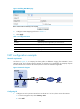
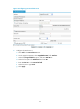
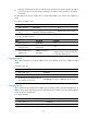
c. On the page that appears as shown in Figure 71, enter 0 in Index, enter 202.38.1.2 in Start
IP Address and enter 202.38.1.3 in End IP Address.
d. Click Apply.
Figure 71 Configuring NAT address pool 0
3. Configure dynamic NAT:
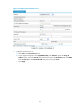
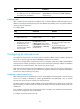
a. Click Add in the Dynamic NAT area.
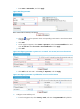
b. On the page that appears, select GigabitEthernet0/1 for Interface and enter 2001 for ACL.
c. Select PAT for Address Transfer.
d. Enter 0 for Address Pool Index.
e. Click Apply.
Figure 72 Configuring dynamic NAT
Internal server configuration example
Network requirements
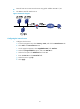
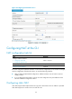
As illustrated in Figure 73, a company provides two Web servers and one FTP server for external users
to access. The internal network address is 10.110.0.0/16. The internal address for the FTP server is
10.110.10.3/16, for the Web server 1 is 10.110.10.1/16, and for the Web server 2 is 10.110.10.2/16. The
company has three public IP addresses from 202.38.1.1/24 through 202.38.1.3/24. Specifically, the
company has the following requirements: