
F3215-HP Load Balancing Module Network Management Configuration Guide-6PW101

134
Verifying the configuration
Use the ping ipv6 3001::0800:0002 command on Router B, response packets can be received.
Configuring static mappings on the IPv4 side and the IPv6 side
Network requirements
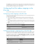
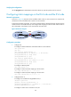
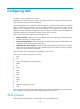
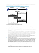
As shown in Figure 84, Router B with IPv6 address 2001::2/64 on an IPv6 network can communicate
with Router A with IPv4 address 8.0.0.2/24 on an IPv4 network.
To meet the preceding requirement, you need to configure LB that is deployed between the IPv4 network
and IPv6 network as a NAT-PT device, and configure static mappings on the IPv4 side and IPv6 side on
LB, so that Router A and Router B can communicate with each other.
Figure 84 Network diagram
Configuration procedure
1. Configure LB:
# Configure interface addresses and enable NAT-PT on the interfaces.
<LB> system-view
[LB] ipv6
[LB] interface gigabitethernet 0/1
[LB-GigabitEthernet0/1] ip address 8.0.0.1 255.255.255.0
[LB-GigabitEthernet0/1] natpt enable
[LB-GigabitEthernet0/1] quit
[LB] interface gigabitethernet 0/2
[LB-GigabitEthernet0/2] ipv6 address 2001::1/64
[LB-GigabitEthernet0/2] natpt enable
[LB-GigabitEthernet0/2] quit
# Configure a NAT-PT prefix.
[LB] natpt prefix 3001::
# Configure a static IPv4/IPv6 mapping on the IPv4 side.
[LB] natpt v4bound static 9.0.0.2 3001::5
# Configure a static IPv4/IPv6 mapping on the IPv6 side.
[LB] natpt v6bound static 2001::2 8.0.0.5
2. Configure Router A:
# Configure an IP address for GigabitEthernet 0/1.
<RouterA> system-view
[RouterA] interface gigabitethernet 0/1
[RouterA-GigabitEthernet0/1] ip address 8.0.0.2 255.255.255.0
[RouterA-GigabitEthernet0/1] quit
# Configure a static route to subnet 9.0.0.0/24.