
F3215-HP Load Balancing Module Network Management Configuration Guide-6PW101

174
RIP configuration example
In this example, Device A is the LB module.
Network requirements
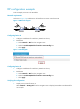
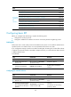
As shown in Figure 118, enable RIP on all interfaces on Device A and Device B.
Figure 118 Network diagram
Configuring Device A
1. Configure IP addresses for interfaces. (Details not shown)
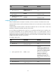
2. Enable RIP:
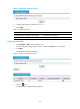
a. Select Network > RIP from the navigation tree.
b. Select the Enable RIP(Enable all interfaces automatically) box.
c. Click Apply.
Figure 119 Enabling RIP
Configuring Device B
1. Configure IP addresses for interfaces. (Details not shown)
2. Enable RIP:
a. Select Network > RIP from the navigation tree.
b. Select the Enable RIP(Enable all interfaces automatically) box.
c. Click Apply.
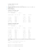
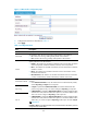
Verifying the configuration
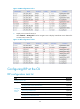
1. Display active routes of Device A:
Select Network > Routing Info from the navigation tree to display learned RIP route destined for
10.0.0.0/8.