
F3215-HP Load Balancing Module Network Management Configuration Guide-6PW101

189
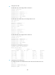
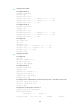
# Display the IP routing table on Router B.
[RouterB] display ip routing-table
Routing Tables: Public
Destinations : 8 Routes : 8
Destination/Mask Proto Pre Cost NextHop Interface
10.2.1.0/24 RIP 100 1 12.3.1.1 GE0/1
11.1.1.0/24 RIP 100 1 12.3.1.1 GE0/1
12.3.1.0/24 Direct 0 0 12.3.1.2 GE0/1
12.3.1.2/32 Direct 0 0 127.0.0.1 InLoop0
16.4.1.0/24 Direct 0 0 16.4.1.1 GE0/2
16.4.1.1/32 Direct 0 0 127.0.0.1 InLoop0
127.0.0.0/8 Direct 0 0 127.0.0.1 InLoop0
127.0.0.1/32 Direct 0 0 127.0.0.1 InLoop0
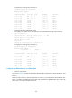
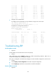
• Configure RIP to filter redistributed routes:
# Configure ACL 2000 on LB to not advertise routes redistributed from RIP 100 to Router B.
[LB] acl number 2000
[LB-acl-basic-2000] rule deny source 10.2.1.1 0.0.0.255
[LB-acl-basic-2000] rule permit
[LB-acl-basic-2000] quit
[LB] rip 200
[LB-rip-200] filter-policy 2000 export rip 100
# Display the IP routing table on Router B.
[RouterB] display ip routing-table
Routing Tables: Public
Destinations : 7 Routes : 7
Destination/Mask Proto Pre Cost NextHop Interface
11.1.1.0/24 RIP 100 1 12.3.1.1 GE0/1
12.3.1.0/24 Direct 0 0 12.3.1.2 GE0/1
12.3.1.2/32 Direct 0 0 127.0.0.1 InLoop0
16.4.1.0/24 Direct 0 0 16.4.1.1 GE0/2
16.4.1.1/32 Direct 0 0 127.0.0.1 InLoop0
127.0.0.0/8 Direct 0 0 127.0.0.1 InLoop0
127.0.0.1/32 Direct 0 0 127.0.0.1 InLoop0
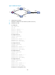
Configuring an additional metric for a RIP interface
1. Network requirements
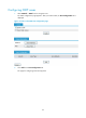
As shown in Figure 124, run RIPv2 is enabled on all the interfaces of LB, Router A, Router B, Router C, and
Rou
ter D.
LB has two links to Router C. The link from Router A to Router C is more stable than that from Router B to
Router C. Configure an additional metric for RIP routes received from GigabitEthernet 0/2 on LB so LB
prefers route 1.1.5.0/24 learned from Router A.