
F3215-HP Load Balancing Module Network Management Configuration Guide-6PW101


191
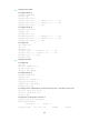
[LB] display rip 1 database
1.0.0.0/8, cost 0, ClassfulSumm
1.1.1.0/24, cost 0, nexthop 1.1.1.1, Rip-interface
1.1.2.0/24, cost 0, nexthop 1.1.2.1, Rip-interface
1.1.3.0/24, cost 1, nexthop 1.1.1.2
1.1.4.0/24, cost 1, nexthop 1.1.2.2
1.1.5.0/24, cost 2, nexthop 1.1.1.2
1.1.5.0/24, cost 2, nexthop 1.1.2.2
The output shows that two RIP routes can reach network 1.1.5.0/24. Their next hops are Router A
(1.1.1.2) and Router B (1.1.2.2), respectively, with the same cost of 2. Router B is the next hop
router to reach network 1.1.4.0/24, with a cost of 1.
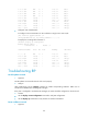
• Configure an additional metric of 3 for RIP-enabled GigabitEthernet 0/2 on LB.
[LB] interface gigabitethernet 0/2
[LB-GigabitEthernet0/2] rip metricin 3
[LB-GigabitEthernet0/2] display rip 1 database
1.0.0.0/8, cost 0, ClassfulSumm
1.1.1.0/24, cost 0, nexthop 1.1.1.1, Rip-interface
1.1.2.0/24, cost 0, nexthop 1.1.2.1, Rip-interface
1.1.3.0/24, cost 1, nexthop 1.1.1.2
1.1.4.0/24, cost 2, nexthop 1.1.1.2
1.1.5.0/24, cost 2, nexthop 1.1.1.2
The output shows that only one RIP route reaches network 1.1.5.0/24, with the next hop as Router
A (1.1.1.2) and a cost of 2.
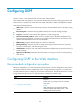
Configuring RIP to advertise a summary route
1. Network requirements
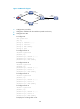
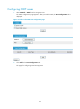
As shown in Figure 125, Router A and Router B run OSPF; Router C ru
ns RIP; and LB runs OSPF and RIP.
Configure RIP to redistribute OSPF routes on LB so Router C can learn routes destined for networks
10 .1.1. 0 / 24 , 10 . 2 .1. 0 / 24 , 10 . 5 .1. 0 / 24 , a n d 10 . 6 .1. 0 / 24 .
To reduce the routing table size of Router C, configure route summarization on LB to advertise only the
summary route 10.0.0.0/8 to Router C.
Figure 125 Network diagram
2. Configuration procedure
• Configure IP addresses for interfaces. (Details not shown.)
Router A
GE0/1
10.2.1.2/24
LB
GE0/1
10.2.1.1/24
GE0/1
11.3.1.2/24
Router C
RIP
OSPF
Router B
GE0/3
10.1.1.2/24
GE0/1
10.1.1.1/24
GE0/2
11.3.1.1/24
GE0/2
11.4.1.2/24
GE0/2
10.6.1.2/24
GE0/2
10.5.1.2/24