
F3215-HP Load Balancing Module Network Management Configuration Guide-6PW101


208
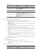
b. Enter 2 for Area ID, select Normal for Area Type, enter 10.3.1.0 for Network Address, select
0.0.0.255 for Network Mask, and click Add Network.
c. Enter 10.5.1.0 for Network Address, select 0.0.0.255 for Network Mask, and click Add
Network.
d. Click Apply.
Verifying the configuration
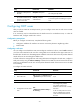
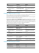
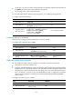
1. Display OSPF neighbor information of Device A:
a. Select Network > OSPF from the navigation tree of Device A.
b. Click Show Peer in the Show Information field.
A neighbor in Full state is displayed in area 0 and area 1. (192.168.1.42 is the router ID of
Device B, and 192.168.1.57 is the router ID of Device C.)
Figure 139 OSPF configuration result I
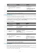
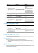
2. Display the routing table of Device A:
Select Network > Routing Info from the navigation tree of Device A. The OSPF routes 3.2.1.0/24,
10.3.1.0/24, 10.4.1.0/24 and 10.5.1.0/24 that are learned after OSPF is enabled are
displayed in the routing table.
Figure 140 OSPF configuration result II
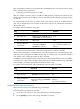
Configuring OSPF at the CLI
OSPF configuration task list
To run OSPF, you must first enable OSPF on the router. Make a proper configuration plan to avoid wrong
settings that can result in route blocking and routing loops.
Complete the following tasks to configure OSPF: