
F3215-HP Load Balancing Module Network Management Configuration Guide-6PW101

244
Router ID: 3.3.3.3 Address: 192.168.1.3 GR State: Normal
State: Full Mode: Nbr is Slave Priority: 2
DR: 192.168.1.1 BDR: 192.168.1.3 MTU: 0
Dead timer due in 39 sec
Neighbor is up for 00:01:41
Authentication Sequence: [ 0 ]
The output shows that LB becomes the DR and Router B becomes the BDR.
The full neighbor state means an adjacency has been established. The 2-way neighbor state
means the two devices are not the DR or BDR, and they do not exchange LSAs.
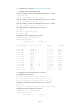
# Display OSPF interface information
[LB] display ospf interface
OSPF Process 1 with Router ID 1.1.1.1
Interfaces
Area: 0.0.0.0
IP Address Type State Cost Pri DR BDR
192.168.1.1 Broadcast DR 1 100 192.168.1.1 192.168.1.3
[RouterB] display ospf interface
OSPF Process 1 with Router ID 2.2.2.2
Interfaces
Area: 0.0.0.0
IP Address Type State Cost Pri DR BDR
192.168.1.2 Broadcast DROther 1 0 192.168.1.1 192.168.1.3
The interface state DROther means the interface is not the DR or BDR.
Configuring OSPF virtual links
1. Network requirements
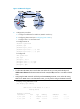
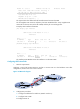
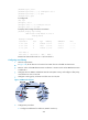
Configure a virtual link between Router B and LB to connect Area 2 to the backbone area. After
configuration, Router B can learn routes to Area 2.
Figure 147 Network diagram
2. Configuration procedure
a. Configure IP addresses for interfaces. (Details not shown.)
b. Configure basic OSPF:
# Configure Router A.