
F3215-HP Load Balancing Module Network Management Configuration Guide-6PW101
288
Two routes 2.2.2.2/32 and 9.1.1.0/24 have been added in the routing table of Router A.
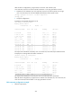
# Display the BGP routing table on Router B.
[RouterB] display bgp routing-table
Total Number of Routes: 4
BGP Local router ID is 3.3.3.3
Status codes: * - valid, ^ - VPNv4 best, > - best, d - damped,
h - history, i - internal, s - suppressed, S - Stale
Origin : i - IGP, e - EGP, ? - incomplete
Network NextHop MED LocPrf PrefVal Path/Ogn
i 2.2.2.2/32 2.2.2.2 0 100 0 ?
*>i 3.1.1.0/24 2.2.2.2 0 100 0 ?
*>i 8.1.1.0/24 3.1.1.2 0 100 0 65008i
* i 9.1.1.0/24 2.2.2.2 0 100 0 ?
The output shows that the route 8.1.1.0 becomes valid with the next hop as Router A.
e. Verify the configuration:
# Ping 8.1.1.1 on Router B.
[RouterB] ping 8.1.1.1
PING 8.1.1.1: 56 data bytes, press CTRL_C to break
Reply from 8.1.1.1: bytes=56 Sequence=1 ttl=254 time=2 ms
Reply from 8.1.1.1: bytes=56 Sequence=2 ttl=254 time=2 ms
Reply from 8.1.1.1: bytes=56 Sequence=3 ttl=254 time=2 ms
Reply from 8.1.1.1: bytes=56 Sequence=4 ttl=254 time=2 ms
Reply from 8.1.1.1: bytes=56 Sequence=5 ttl=254 time=2 ms
--- 8.1.1.1 ping statistics ---
5 packet(s) transmitted
5 packet(s) received
0.00% packet loss
round-trip min/avg/max = 2/2/2 ms
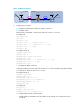
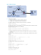
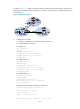
BGP and IGP synchronization configuration example
1. Network requirements
As shown in Figure 163, all dev
ices of company A reside in AS 65008 while all devices of company B
reside in AS 65009. AS 65008 and AS 65009 are connected through Router A and LB. It is required that
Router A can access network 9.1.2.0/24 in AS 65009, and Router B can access network 8.1.1.0/24 in
AS 65008.