
F3215-HP Load Balancing Module Network Management Configuration Guide-6PW101

289
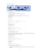
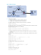
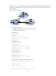
Figure 163 Network diagram
2. Configuration procedure
a. Configure IP addresses for interfaces. (Details not shown.)
b. Configure OSPF:
Enable OSPF in AS 65009, so that LB can obtain the route to 9.1.2.0/24.
# Configure LB.
<LB> system-view
[LB] ospf 1
[LB-ospf-1] area 0
[LB-ospf-1-area-0.0.0.0] network 2.2.2.2 0.0.0.0
[LB-ospf-1-area-0.0.0.0] network 9.1.1.0 0.0.0.255
[LB-ospf-1-area-0.0.0.0] quit
[LB-ospf-1] quit
# Configure Router B.
<RouterB> system-view
[RouterB] ospf 1
[RouterB-ospf-1] import-route direct
[RouterB-ospf-1] area 0
[RouterB-ospf-1-area-0.0.0.0] network 9.1.1.0 0.0.0.255
[RouterB-ospf-1-area-0.0.0.0] quit
[RouterB-ospf-1] quit
c. Configure the EBGP connection:
Configure the EBGP connection and inject network 8.1.1.0/24 to the BGP routing table of Router
A, so that LB can obtain the route to 8.1.1.0/24.
# Configure Router A.
<RouterA> system-view
[RouterA] bgp 65008
[RouterA-bgp] router-id 1.1.1.1
[RouterA-bgp] peer 3.1.1.1 as-number 65009
[RouterA-bgp] network 8.1.1.0 24
[RouterA-bgp] quit
# Configure LB.
[LB] bgp 65009
[LB-bgp] router-id 2.2.2.2
[LB-bgp] peer 3.1.1.2 as-number 65008
d. Configure BGP and IGP synchronization:
{ Configure BGP to redistribute routes from OSPF on LB, so Router A can obtain the route to
9.1.2.0/24.
Router A
AS 65008
GE0/2
3.1.1.1/24
Router BLB
AS 65009
GE0/1
8.1.1.1/24
GE0/2
3.1.1.2/24
GE0/1
9.1.1.1/24
GE0/1
9.1.1.2/24
Loop0
1.1.1.1/32
Loop0
2.2.2.2/32
Loop0
3.3.3.3/32
EBGP OSPF
GE0/2
9.1.2.1/24