
F3215-HP Load Balancing Module Network Management Configuration Guide-6PW101

291
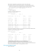
Reply from 9.1.2.1: bytes=56 Sequence=5 ttl=254 time=47 ms
--- 9.1.2.1 ping statistics ---
5 packet(s) transmitted
5 packet(s) received
0.00% packet loss
round-trip min/avg/max = 15/37/47 ms
[RouterB] ping -a 9.1.2.1 8.1.1.1
PING 8.1.1.1: 56 data bytes, press CTRL_C to break
Reply from 8.1.1.1: bytes=56 Sequence=1 ttl=254 time=2 ms
Reply from 8.1.1.1: bytes=56 Sequence=2 ttl=254 time=2 ms
Reply from 8.1.1.1: bytes=56 Sequence=3 ttl=254 time=2 ms
Reply from 8.1.1.1: bytes=56 Sequence=4 ttl=254 time=2 ms
Reply from 8.1.1.1: bytes=56 Sequence=5 ttl=254 time=2 ms
--- 8.1.1.1 ping statistics ---
5 packet(s) transmitted
5 packet(s) received
0.00% packet loss
round-trip min/avg/max = 2/2/2 ms
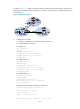
BGP load balancing configuration example
1. Network requirements
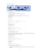
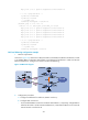
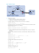
As shown in Figure 164, all dev
ices run BGP, LB resides in AS 65008, and Router B and Router A reside
in AS 65009. EBGP runs between LB and Router B, and between LB and Router C. IBGP runs between
Router B and Router A. Configure two routes on LB for load balancing.
Figure 164 Network diagram
2. Configuration procedure
a. Configure IP addresses for interfaces. (Details not shown.)
b. Configure BGP connections:
{ On LB, establish EBGP connections with Router B and Router A, respectively; configure BGP to
advertise network 8.1.1.0/24 to Router B and Router A, so Router B and Router A can access the
internal network connected to LB.