
F3215-HP Load Balancing Module Network Management Configuration Guide-6PW101


315
Item Descri
p
tion
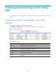
Next Hop
Enter the next hop IP address.
The Web interface supports setting only one outbound interface, next hop, default
outbound interface, or default next hop. If you configure two interfaces or next hops at
the CLI, the Web interface displays only one. To display the other interface or next hop,
first delete the one that is displayed.
Default Next Hop
Enter the default next hop IP address.
Outbound Interface
Enter the outbound interface. (This option is available after you click Show Advanced.)
Non-P2P interfaces (broadcast and NBMA interfaces, such as Ethernet and
virtual-template interfaces) may have multiple next hops, and packets may not be
forwarded successfully.
Default Outbound
Interface
Enter the default outbound interface. (This option is available after you click Show
Advanced.)
Non-P2P interfaces (broadcast and NBMA interfaces, such as Ethernet and
virtual-template interfaces) may have multiple next hops, and packets may not be
forwarded successfully.
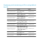
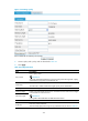
Table 30 IP preference values and keywords
Preference value Ke
y
word
0 routine
1 priority
2 immediate
3 flash
4 flash-override
5 critical
6 internet
7 network
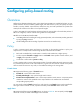
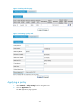
Configuring a policy node
To configure a node for an existing policy, use one of the following methods:
• Click Add in Figure 171 to enter the poli
cy configuration page as shown in Figure 172. Enter the
name of the policy in the Policy Name field, and then configure its node.
• Click the policy name link in Figure 171 to enter the polic
y node list page, as shown in Figure 173.
You can create, modify, or remove a policy node on the page. To create a policy node, click Add
to enter the policy node configuration page (the policy name cannot be modified), as shown
in Figure 174.
For descriptions of the configuration items, see "Creating a poli
cy and a policy
node."