
F3215-HP Load Balancing Module Network Management Configuration Guide-6PW101


26
Configuration example
Network requirements
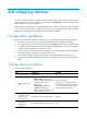
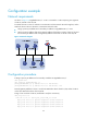
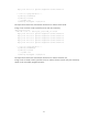
As shown in Figure 12, GigabitEthernet 0/1 on LB is connected to a LAN comprising two segments:
172.16.1.0/24 and 172.16.2.0/24.
To enable the hosts on the two subnets to communicate with the external network through LB, and to
enable the hosts on the two subnets to communicate with each other:
• Assign a primary IP address and a secondary IP address to GigabitEthernet 0/1 on LB.
• Set the primary IP address of LB as the gateway address of the hosts on subnet 172.16.1.0/24, and
the secondary IP address of LB as the gateway address of the hosts on subnet 172.16.2.0/24.
Figure 12 Network diagram
Configuration procedure
# Assign a primary IP address and a secondary IP address to GigabitEthernet 0/1.
<LB> system-view
[LB] interface gigabitethernet 0/1
[LB-GigabitEthernet0/1] ip address 172.16.1.1 255.255.255.0
[LB-GigabitEthernet0/1] ip address 172.16.2.1 255.255.255.0 sub
# Set the gateway address to 172.16.1.1 on the hosts attached to subnet 172.16.1.0/24, and to 172.16.2.1
on the hosts attached to subnet 172.16.2.0/24.
# Ping a host on subnet 172.16.1.0/24 from LB to verify the connectivity.
<LB> ping 172.16.1.2
PING 172.16.1.2: 56 data bytes, press CTRL_C to break
Reply from 172.16.1.2: bytes=56 Sequence=1 ttl=255 time=25 ms
Reply from 172.16.1.2: bytes=56 Sequence=2 ttl=255 time=27 ms
Reply from 172.16.1.2: bytes=56 Sequence=3 ttl=255 time=26 ms
Reply from 172.16.1.2: bytes=56 Sequence=4 ttl=255 time=26 ms