
F3215-HP Load Balancing Module Network Management Configuration Guide-6PW101

399
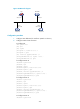
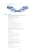
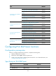
Figure 203 Network diagram
Configuration procedure
1. Configure IPv6 addresses for interfaces. (Details not shown.)
2. Configure OSPFv3 basic functions:
# Configure LB.
<LB> system-view
[LB] ipv6
[LB] ospfv3
[LB-ospfv3-1] router-id 1.1.1.1
[LB-ospfv3-1] quit
[LB] interface gigabitethernet 0/1
[LB-GigabitEthernet0/1] ospfv3 1 area 0
[LB-GigabitEthernet0/1] quit
# Configure Router B.
<RouterB> system-view
[RouterB] ipv6
[RouterB] ospfv3
[RouterB-ospfv3-1] router-id 2.2.2.2
[RouterB-ospfv3-1] quit
[RouterB] interface gigabitethernet 0/1
[RouterB-GigabitEthernet0/1] ospfv3 1 area 0
[RouterB-GigabitEthernet0/1] quit
# Configure Router C.
<RouterC> system-view
[RouterC] ipv6
[RouterC] ospfv3
[RouterC-ospfv3-1] router-id 3.3.3.3
[RouterC-ospfv3-1] quit
[RouterC] interface gigabitethernet 0/1
[RouterC-GigabitEthernet0/1] ospfv3 1 area 0
[RouterC-GigabitEthernet0/1] quit
# Configure Router A.
<RouterA> system-view
LB
Router C
Router B
Router A
GE0/1
2001::1/64
GE0/1
2001::2/64
GE0/1
2001::3/64
GE0/1
2001::4/64