
F3215-HP Load Balancing Module Network Management Configuration Guide-6PW101


53
VLAN interface configuration example
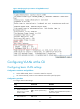
1. Network requirements
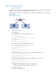
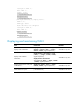
As shown in Figure 37, PC
A is assigned to VLAN 5. PC B is assigned to VLAN 10. The PCs belong to
different IP subnets and cannot communicate with each other.
Configure VLAN interfaces on LB and configure PC A and PC B to enable Layer 3 communication
between them.
Figure 37 Network diagram
2. Configuration procedure
a. Configure LB:
# Create VLAN 5 and assign GigabitEthernet 0/1 to it.
<LB> system-view
[LB] interface gigabitethernet 0/1
[LB-GigabitEthernet0/1] port link-mode bridge
[LB-GigabitEthernet0/1] quit
[LB] vlan 5
[LB-vlan5] port gigabitethernet 0/1
# Create VLAN 10 and assign GigabitEthernet 0/2 to it.
[LB] interface gigabitethernet 0/2
[LB-GigabitEthernet0/2] port link-mode bridge
[LB-GigabitEthernet0/2] quit
[LB-vlan5] vlan 10
[LB-vlan10] port gigabitethernet 0/2
[LB-vlan10] quit
# Create VLAN-interface 5 and configure its IP address as 192.168.0.10/24.
[LB] interface vlan-interface 5
[LB-Vlan-interface5] ip address 192.168.0.10 24
[LB-Vlan-interface5] quit
# Create VLAN-interface 10 and configure its IP address as 192.168.1.20/24.
[LB] interface vlan-interface 10
[LB-Vlan-interface10] ip address 192.168.1.20 24
[LB-Vlan-interface10] return
b. Configure the default gateway of PC A as 192.168.0.10.
c. Configure the default gateway of PC B as 192.168.1.20.
3. Verifying the configuration
a. The PCs can ping each other.
LB
PC A
PC B
Vlan-Int5 Vlan-Int10
GE0/1
192.168.0.10/24 192.168.1.20/24
VLAN 5 VLAN 10
192. 168.0.1/24 192. 168.1.1/24
GE0/2