
F3215-HP Load Balancing Module Network Management Configuration Guide-6PW101


56
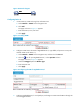
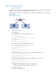
Figure 38 Network diagram
2. Configuration procedure
a. Configure LB A:
# Create VLAN 100, and assign port GigabitEthernet 0/1 to VLAN 100.
<LBA> system-view
[LBA] interface gigabitethernet 0/1
[LBA-GigabitEthernet0/1] port link-mode bridge
[LBA-GigabitEthernet0/1]quit
[LBA] vlan 100
[LBA-vlan100] port gigabitethernet 0/1
[LBA-vlan100] quit
# Create VLAN 200, and assign port GigabitEthernet 0/2 to VLAN 200.
[LBA] interface gigabitethernet 0/2
[LBA-GigabitEthernet0/2] port link-mode bridge
[LBA-GigabitEthernet0/2]quit
[LBA] vlan 200
[LBA-vlan200] port gigabitethernet 0/2
[LBA-vlan200] quit
# Configure port GigabitEthernet 0/3 as a trunk port, and assign it to VLANs 100 and 200, to
enable GigabitEthernet 0/3 to forward traffic of VLANs 100 and 200 to LB B.
[LBA] interface gigabitethernet 0/3
[LBA-GigabitEthernet0/3] port link-mode bridge
[LBA-GigabitEthernet0/3] port link-type trunk
[LBA-GigabitEthernet0/3] port trunk permit vlan 100 200
Please wait... Done.
b. Configure LB B as you configure LB A.
c. Configure Host A and Host C to be on the same IP subnet, 192.168.100.0/24, for example.
Configure Host B and Host D to be on the same IP subnet, 192.168.200.0/24, for example.
3. Verifying the configuration
a. Host A and Host C can ping each other successfully, but they both fail to ping Host B. Host B
and Host D can ping each other successfully, but they both fail to ping Host A.
b. Determine whether the configuration is successful by displaying relevant VLAN information.
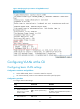
# Display information about VLANs 100 and 200 on LB A.
[LBA-GigabitEthernet0/3] display vlan 100
VLAN ID: 100
VLAN Type: static
Route Interface: not configured