
F3215-HP Load Balancing Module Network Management Configuration Guide-6PW101

59
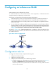
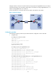
b. Configure the downlink ports, for example, the ports connecting Device B to hosts in Figure 39,
to operate in host mode, so that downlink ports can be automatically added to the
isolate-user-VLAN associated with the secondary VLAN.
For more information about the promiscuous and host mode commands, see Network
Management Command Reference.
4. Associate the isolate-user-VLAN with the specified secondary VLANs.
Configuration guidelines
• After you complete the isolate-user-VLAN configurations, make sure the isolate-user-VLAN is the
PVID of the uplink port and the secondary VLAN is the PVID of the downlink port. For hybrid ports
that have been assigned to the isolate-user-VLAN and secondary VLANs in tagged mode, HP
recommends that you assign these ports to these VLANs in untagged mode.
• When you configure uplink and downlink ports, besides the method of configuring them to operate
in promiscuous mode or host mode, you can configure them in the following method: assign the
port to an isolate-user-VLAN or secondary VLAN, and make sure the PVID of at least one port is the
isolate-user-VLAN or secondary VLAN. More specifically, configure the link type of the uplink port
as hybrid, assign it to the isolate-user-VLAN and secondary VLANs in untagged mode, and
configure the isolate-user-VLAN as its PVID. Configure the link type of the downlink port as hybrid,
assign the port to the isolate-user-VLAN and the secondary VLAN of the port in untagged mode,
and configure the secondary VLAN as its PVID. For more information, see "Configuring VLANs."
When you configure uplink and downlink ports in the method, the ports in each secondary VLAN
are not isolated at Layer 2.
• HP recommends that you complete the isolate-user-VLAN configuration by configuring the ports to
operate in promiscuous mode or host mode. This method is more flexible and easier to use.
• An isolate-user-VLAN will automatically synchronize the dynamic MAC address entries of the
associated secondary VLANs.
• To enable users in the isolate-user-VLAN to communicate with other networks at Layer 3, configure
VLAN interfaces for the isolate-user-VLAN and the secondary VLANs, and configure the gateway IP
address for the isolate-user-VLAN interface (you do not need to configure IP addresses for the
secondary VLAN interfaces).
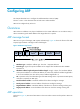
Configuration procedure
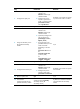
To configure an isolate-user-VLAN:
Ste
p
Command
Remarks
1. Enter system view.
system-view N/A
2. Create a VLAN and enter
VLAN view.
vlan vlan-id N/A
3. Configure the VLAN as an
isolate-user-VLAN.
isolate-user-vlan enable
By default, no isolate-user-VLAN is
configured.
4. Return to system view.
quit
N/A
5. Create secondary VLANs.
vlan { vlan-id1 [ to vlan-id2 ] | all }
N/A
6. Return to system view.
quit N/A