
F3215-HP Load Balancing Module Network Management Configuration Guide-6PW101

61
Displaying and maintaining isolate-user-VLAN
Task Command
Remarks
Display the mapping between an
isolate-user-VLAN and its secondary
VLANs.
display isolate-user-vlan
[ isolate-user-vlan-id ] [ | { begin |
exclude | include } regular-expression ]
Available in any view.
Isolate-user-VLAN configuration example
(approach 1)
Network requirements
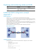
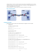
As shown in Figure 41, connect the device to downstream devices LB A and LB B.
Configure VLAN 5 on LB A as an isolate-user-VLAN, assign uplink port GigabitEthernet 0/3 to VLAN 5,
and associate VLAN 5 with secondary VLANs VLAN 2 and VLAN 3. Assign GigabitEthernet 0/2 to
VLAN 2 and GigabitEthernet 0/1 to VLAN 3.
Configure VLAN 6 on LB B as an isolate-user-VLAN, assign uplink port GigabitEthernet 0/3 to VLAN 6,
and associate VLAN 6 with secondary VLANs VLAN 3 and VLAN 4. Assign GigabitEthernet 0/1 to
VLAN 3 and GigabitEthernet 0/2 to VLAN 4.
As far as the device is concerned, LB A only has VLAN 5 and LB B only has VLAN 6.
Figure 40 Network diagram
Configuration procedure
The following procedure provides only the details about the configuration on LB A and LB B.
1. Configure LB A:
# Configure the isolate-user-VLAN.
<LBA> system-view
[LBA] vlan 5
[LBA-vlan5] isolate-user-vlan enable
[LBA-vlan5] quit
# Create secondary VLANs.