
F3215-HP Load Balancing Module Network Management Configuration Guide-6PW101


80
[Switch-Ethernet1/3] port-isolate enable group 2
[Switch-Ethernet1/3] interface ethernet 1/1
[Switch-Ethernet1/1] port-isolate enable group 2
[Switch-Ethernet1/1] interface ethernet 1/2
[Switch-Ethernet1/2] port-isolate uplink-port group 2
2. Configure LB:
# Specify the IP address of GigabitEthernet 0/2.
<LB> system-view
[LB] interface gigabitethernet 0/2
[LB-GigabitEthernet0/2] ip address 192.168.10.100 255.255.0.0
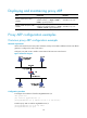
The ping operation from Host A to Host B is unsuccessful because they are isolated at Layer 2 and
Layer 3.
# Configure local proxy ARP to allow communication between Host A and Host B at Layer 3.
[LB-GigabitEthernet0/2] local-proxy-arp enable
The ping operation from Host A to Host B is successful after the configuration.
Local proxy ARP configuration example in isolate-user-VLAN
Network requirements
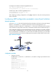
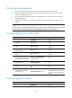
As shown in Figure 49, the switch is attached to LB. VLAN 5 on the switch is an isolate-user-VLAN, which
includes uplink port Ethernet 1/2 and two secondary VLANs, VLAN 2 and VLAN 3. Ethernet 1/3
belongs to VLAN 2, and Ethernet 1/1 belongs to VLAN 3. Host A belongs to VLAN 2 and connects to
Ethernet 1/3 of the switch. Host B belongs to VLAN 3 and connects to Ethernet 1/1 of the switch.
As Host A and Host B belong to different secondary VLANs, they are isolated at Layer 2. Configure local
proxy ARP on LB to implement Layer 3 communication between Host A and Host B.
Figure 49 Network diagram
Configuration procedure
1. Configure the switch:
# Configure VLAN 5 as an isolate-user-VLAN.
<Switch> system-view
[Switch] vlan 5