
F3215-HP Load Balancing Module Network Management Configuration Guide-6PW101


86
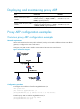
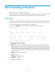
Configuration prerequisites
• The ingress interface and egress interface on the switch belong to different VLANs.
• The two ten-GigabitEthernet interfaces at both ends of the link between the switch and the LB
module are configured as trunk.
• The operating mode of the LB module's ten-GigabitEthernet port that connects to the switch is
configured as Layer 2.
• Configure VLAN interfaces with the same numbers as VLANs created on the switch for the LB
module.
NOTE:
To achieve Layer 3 forwarding between VLANs, you can create these VLANs on the switch and confi
g
ure
the same number of subinterfaces for the ten-GigabitEthernet interface on the LB module.
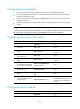
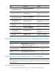
Configuring the ports of the switch
Ste
p
Command
Remarks
1. Enter system view.
system-view
N/A
2. Create a VLAN and enter
VLAN view.
vlan vlan-id N/A
3. Assign the access ports to the
VLAN.
port interface-list
By default, all ports belong to
VLAN 1.
4. Create another VLAN and
enter VLAN view.
vlan vlan-id N/A
5. Assign the access ports to the
VLAN.
port interface-list
By default, all ports belong to
VLAN 1.
6. Enter the view of the
ten-GigabitEthernet interface
that connects to the LB module.
interface Ten-GigabitEthernet
interface-number
N/A
7. Configure the link type of the
interface as trunk.
port link-type trunk N/A
8. Assign the trunk port to the two
VLANs.
port trunk permit vlan { vlan-id-list |
all }
N/A
9. Configure the default VLAN
for the trunk port.
port trunk pvid vlan vlan-id
Optional.
The default VLAN cannot be one
of the previously configured two
VLANs.
Configuring the LB module
Ste
p
Command
Remarks
1. Enter system view.
system-view
N/A