
F3215-HP Load Balancing Module Security Configuration Guide-6PW101

169
Configuration example
Network requirements
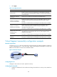
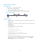
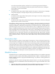
As shown in Figure 71, configure devices as follows:
• LB module connects to Host and Router.
• NAT is enabled on GigabitEthernet 0/2 of LB module.
• Configure IP virtual fragment reassembly on security zone Trust of LB module.
Figure 71 Network diagram
Configuration procedure
1. As shown in Figure 71, assign IP addresses to the interfaces and add them into security zones.
(Details not shown.)
2. Configure the host:
# Configure a route so that the Host, LB module, and Router can communicate with each other.
(Details not shown.)
3. Configure LB module
# Configure NAT and IP virtual fragment reassembly.
<LB> system-view
[LB] nat static 10.1.1.1 11.2.2.3
[LB] interface gigabitethernet 0/2
[LB-GigabitEthernet0/2] nat outbound static
[LB-GigabitEthernet0/2] quit
[LB-GigabitEthernet0/2] ip virtual-reassembly
# Configure IP virtual fragment reassembly on security zone Trust.
[LB] zone name trust
[LB-zone-trust] ip virtual-reassembly
With the IP virtual fragment reassembly feature, LB module checks, sequences, and caches
fragments that do not arrive in order at GigabitEthernet 0/2. You can use the display ip
virtual-reassembly command to view related information.