HP Load Balancing Module System Maintenance Configuration Guide Part number: 5998-4221 Software version: Feature 3221 Document version: 6PW100-20130326
Legal and notice information © Copyright 2013 Hewlett-Packard Development Company, L.P. No part of this documentation may be reproduced or transmitted in any form or by any means without prior written consent of Hewlett-Packard Development Company, L.P. The information contained herein is subject to change without notice.
Contents Using ping, tracert, and system debugging ··············································································································· 1 Ping ····················································································································································································· 1 Using a ping command to test network connectivity ···························································································· 1 Ping example
Configuring the source address for user logging packets ················································································ 41 Exporting user logs ················································································································································ 41 Displaying and maintaining user logging ·········································································································· 42 User logging configuration example ···················
Renaming a file······················································································································································ 76 Copying a file ························································································································································ 77 Moving a file·························································································································································· 77 D
Subscription service ············································································································································ 101 Related information ······················································································································································ 101 Documents ···························································································································································· 101
Using ping, tracert, and system debugging Use the ping, tracert, and system debugging utilities to test network connectivity and identify network problems. Ping, tracert, and system debugging utilities can be used only at the CLI. Ping The ping utility sends ICMP echo requests (ECHO-REQUEST) to the destination device. Upon receiving the requests, the destination device responds with ICMP echo replies (ECHO-REPLY) to the source device.
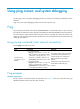
Figure 1 Network diagram Configuration procedure # Use the ping command on LB to test connectivity to Device B. ping 1.1.2.2 PING 1.1.2.2: 56 data bytes, press CTRL_C to break Reply from 1.1.2.2: bytes=56 Sequence=1 ttl=254 time=205 ms Reply from 1.1.2.2: bytes=56 Sequence=2 ttl=254 time=1 ms Reply from 1.1.2.2: bytes=56 Sequence=3 ttl=254 time=1 ms Reply from 1.1.2.2: bytes=56 Sequence=4 ttl=254 time=1 ms Reply from 1.1.2.2: bytes=56 Sequence=5 ttl=254 time=1 ms --- 1.1.2.
1.1.1.1 Reply from 1.1.2.2: bytes=56 Sequence=4 ttl=254 time=1 ms Record Route: 1.1.2.1 1.1.2.2 1.1.1.2 1.1.1.1 Reply from 1.1.2.2: bytes=56 Sequence=5 ttl=254 time=1 ms Record Route: 1.1.2.1 1.1.2.2 1.1.1.2 1.1.1.1 --- 1.1.2.2 ping statistics --5 packet(s) transmitted 5 packet(s) received 0.00% packet loss round-trip min/avg/max = 1/11/53 ms The test procedure with the ping –r command (see Figure 1) is as follows: 1.
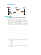
Figure 2 Traceroute operation Tracert uses received ICMP error messages to get the IP addresses of devices. As shown in Figure 2, tracert works as follows: 1. The source device (Device A) sends a UDP packet with a TTL value of 1 to the destination device (Device D). The destination UDP port is not used by any application on the destination device. 2.
hoplimit-expires enable command on the devices. For more information about this command, see Network Management Command Reference. • Enable sending of ICMPv6 destination unreachable packets on the destination device. If the destination device is an HP device, execute the ipv6 unreachables enable command. For more information about this command, see Network Management Command Reference. Using a tracert command to identify failed or all nodes in a path Execute tracert commands in any view.
Figure 3 Relationship between the protocol and screen output switch Debugging a feature module Output from debugging commands is memory intensive. To guarantee system performance, enable debugging only for modules that are in an exceptional condition. When debugging is complete, use the undo debugging all command to disable all the debugging functions. Configure the debugging, terminal debugging and terminal monitor commands before you can display detailed debugging information on the terminal.
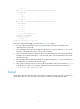
Ping and tracert example Network requirements As shown in Figure 4, LB failed to Telnet Device B. Determine whether LB and Device B can reach each other. If they cannot reach each other, locate the failed nodes in the network. Figure 4 Network diagram Configuration procedure 1. Use the ping command to test connectivity between LB and Device B. ping 1.1.2.2 PING 1.1.2.2: 56 data bytes, press CTRL_C to break Request time out Request time out Request time out Request time out Request time out --- 1.
# Use the debugging ip icmp command on LB and Device B to verify that they can send and receive the specific ICMP packets, or use the display ip routing-table command to verify the availability of active routes between LB and Device B.
Configuring the information center Information center can be configured only at the CLI. Overview The information center collects and classifies system information as follows: • Receives system information including log, trap, and debug information from source modules. • Outputs the information to different information channels, according to output rules. • Outputs information to different destinations, based on channel-to-destination associations.
Severity Severity value Description Corresponding keyword in commands Alert 1 Action must be taken immediately to solve a serious problem. For example, traffic on an interface exceeds the upper limit. alerts Critical 2 Critical condition. For example, the device temperature exceeds the upper limit, the power module fails or the fan tray fails. critical Error 3 Error condition. For example, the link state changes or a storage card is unplugged. errors Warning 4 Warning condition.
Default output rules of system information A default output rule specifies the system information source modules, information type, and severity levels for an output destination. Table 3 shows the default output rules.
Table 4 System information formats Output destination Format Example Console, monitor terminal, logbuffer, trapbuffer, SNMP module, or log file timestamp sysname module/level/digest: content %Jun 26 17:08:35:809 2012 Sysname SHELL/4/LOGIN: VTY login from 1.1.1.1. • HP format: • HP format: Log host timestamp Sysname %%vvmodule/level /digest: source content <189>Oct 9 14:59:04 2012 Sysname %%10SHELL/5/SHELL_LOGIN(l): VTY logged in from 192.168.1.21.
Field Description Module This field specifies source module name. You can execute the info-center source ? command in system view to view the module list. Level (severity) System information is divided into eight severity levels, from 0 to 7. See Table 1 for more information about severity levels. You cannot change the system information levels generated by modules. However, you can use the info-center source command to control the output of system information based on severity levels.
Timestamp parameters iso Description Example Timestamp format stipulated in ISO 8601. <189>2012-05-30T06:42:44 Sysname %%10FTPD/5/FTPD_LOGIN(l): User ftp (192.168.1.23) has logged in successfully. Only system information that is sent to the log host supports this parameter. No timestamp is included. none All system information supports this parameter. no-year-date Current date and time without year information, in the format of mm dd hh:mm:ss:xxx.
Step Command Remarks Optional. 3. Name the channel with a specified channel number. info-center channel channel-number name channel-name 4. Configure an output channel for the console. info-center console channel { channel-number | channel-name } 5. Configure an output rule for the console.
Step Command Remarks Optional. 4. 5. Configure an output channel for the monitor terminal. info-center monitor channel { channel-number | channel-name } Configure an output rule for the monitor terminal.
Step Command Remarks info-center source { module-name | default } channel { channel-number | channel-name } [ debug { level severity | state state } * | log { level severity | state state } * | trap { level severity | state state } * ] * Optional. 4. Configure an output rule for the log host. 5. Specify the source IP address for the log information.
Step 4. 5. Command Configure an output channel for the trap buffer and set the buffer size. info-center trapbuffer [ channel { channel-number | channel-name } | size buffersize ] * Configure an output rule for the trap buffer. info-center source { module-name | default } channel { channel-number | channel-name } [ debug { level severity | state state } * | log { level severity | state state } * | trap { level severity | state state } * ] * Remarks Optional.
Outputting system information to the SNMP module The SNMP module only receives trap information, and discards log and debug information. To monitor the device running status, trap information is usually sent to the SNMP network management system (NMS). For this purpose, you must configure output of traps to the SNMP module, and set the trap sending parameters for the SNMP module. For more information about SNMP, see "Configuring SNMP.
Step Command 2. Enable the information center. info-center enable 3. Name the channel with a specified channel number. info-center channel channel-number name channel-name Configure an output channel for the Web interface. info-center syslog channel { channel-number | channel-name } Configure an output rule for the Web interface.
Step Command Remarks Optional. 5. Configure the maximum size of the log file. The default setting is 10 MB. info-center logfile size-quota size To ensure normal operation of the device, set the size argument to a value between 1 MB and 10 MB. Optional. 6. Configure the directory to save the log file.
Saving security logs into the security log file If this feature is enabled, the system first outputs security logs to the security log file buffer, and then saves the logs in the security log file buffer into the security log file at a specified interval (the security log administrator can also manually save security logs into the log file). After the logs are saved, the buffer is cleared immediately. The size of the security log file is limited.
Task Command Remarks Optional. Change the directory of the security log file. info-center security-logfile switch-directory dir-name By default, the security log file is saved in the seclog directory under the root directory of the storage device. If the device has been partitioned, the security log file is saved in the seclog directory in the second partition of the storage device. Available in user view. Display contents of the security log file buffer.
Task Command Remarks • Display the contents of the specified file: more file-url • Display information about all files and folders: dir [ /all ] [ file-url ] • Create a folder in a specified directory on the storage medium: mkdir directory • Change the current working directory: cd { directory | .. | / } • Display the current path: Perform these operations to the security log file.
Task Command Remarks • Establish a connection to an IPv4 SFTP server and enter SFTP client view: sftp server [ port-number ] [ vpn-instance vpn-instance-name ] [ prefer-compress { zlib | zlib-openssh } | prefer-ctos-cipher { 3des | aes128 | des } | prefer-ctos-hmac { md5 | md5-96 | sha1 | sha1-96 } | prefer-kex { dh-group-exchange | dh-group1 | dh-group14 } | prefer-stoc-cipher { 3des | aes128 | des } | prefer-stoc-hmac { md5 | md5-96 | sha1 | sha1-96 } ] * • Establish a connection to an IPv6 (Optional.
Step Command Remarks 1. Enter system view. system-view N/A 2. Enable synchronous information output. info-center synchronous Disabled by default. Disabling an interface from generating link up/down logging information By default, all interfaces generate link up or link down log information when the state changes. In some cases, you might want to disable specific interfaces from generating this information. For example: • You are concerned only about the states of some interfaces.
Task Command Remarks Display a summary of the log buffer. display logbuffer summary [ level severity ] [ | { begin | exclude | include } regular-expression ] Available in any view. Display the content of the log file buffer. display logfile buffer [ | { begin | exclude | include } regular-expression ] Available in any view. Display the log file configuration. display logfile summary [ | { begin | exclude | include } regular-expression ] Available in any view.
[LB] info-center source arp channel console log level informational state on [LB] info-center source ip channel console log level informational state on [LB] quit # Enable the display of log information on the console. (This function is enabled by default.) terminal monitor Info: Current terminal monitor is on. terminal logging Info: Current terminal logging is on.
a. b. Log in to the log host as a root user. Create a subdirectory named LB in directory /var/log/, and then create file info.log in the LB directory to save logs from the LB. # mkdir /var/log/LB # touch /var/log/LB/info.log c. Edit the file syslog.conf in directory /etc/ and add the following contents. # LB configuration messages local4.info /var/log/LB/info.log In this configuration, local4 is the name of the logging facility that the log host uses to receive logs. info is the informational level.
# Specify the host 1.2.0.1/16 as the log host, use the channel loghost to output log information (optional, loghost by default), and specify local5 as the logging facility. [LB] info-center loghost 1.2.0.1 channel loghost facility local5 # Configure an output rule to output to the log host the log information that has a severity level of at least informational.
Figure 9 Network diagram Configuration considerations The configuration in this example includes two parts: 1. Log in to the LB as the system administrator { { { 2. Enable saving of security logs into the security log file and set the saving interval to one hour. Create a local user seclog with the password 123123123123, and authorize this user as the security log administrator.
# According to the network plan, the user will log in to the LB through SSH or Telnet, so configure the authentication mode of the VTY user interface as scheme. [LB] display user-interface vty ? INTEGER<0-4> Specify one user terminal interface The output shows that the LB supports five VTY user interfaces, which are numbered 0 through 4. [LB] user-interface vty 0 4 [LB-ui-vty0-4] authentication-mode scheme [LB-ui-vty0-4] quit 2.
# Mannually save the contents of the security log file buffer into the security log file. security-logfile save Info: Save all the contents in the security log buffer into file cfa0:/securitylog/seclog.log successfully. # Display the contents of the security log file. more securitylog/seclog.log %@157 Nov 2 16:12:01:750 2012 LB SHELL/4/LOGIN: Trap 1.3.6.1.4.1.25506.2.2.1.1.3.0.1: login from Console %@158 Nov 2 16:12:01:750 2012 LB SHELL/5/SHELL_LOGIN:Console logged in from con0.
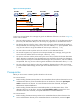
Managing logs This chapter describes how to manage various types of logs. Configuring syslog Syslog can be configured only in the Web interface. The syslog module allows you to set parameters for the information center. The information center classifies and manages system information and it can output log information to the Web interface and log hosts. To configure syslog: 1. Select Log Report > Syslog from the navigation tree to enter the page as shown in Figure 10.
Figure 10 Syslog 2. Configure syslog settings as described in Table 7. 3. Click Apply. Table 7 Configuration items Item Description Log Buffer Size Set the number of syslogs that can be stored in the log buffer. Syslogs that can be stored in the log buffer include system logs, connection limit logs, attack prevention logs, and blacklist logs.
Item Description Log Host 1 Log Host IP Address Log Host 2 Set the address (IPv4 address, host name, or IPv6 address), port number and the VPN instance. Log Host 3 You can report log information to log hosts in the format of syslog. You can specify up to four syslog log hosts. Log Host 4 You can specify up to four syslog log hosts. Set the refresh period on the log information displayed on the log report Web interface.
Field Description Prot Protocol. Operator Indicates the reason why the flow ended. Reserved For future applications. Table 9 Packet format in user logging version 3.0 Field Description Prot Protocol. Operator Indicates the reason why the flow ended. IpVersion IP packet version. TosIPv4 ToS field of the IPv4 packet. SourceIP Source IP address. SrcNatIP Source IP address after Network Address Translation (NAT). DestIP Destination IP address. DestNatIP Destination IP address after NAT.
Figure 11 User logging 2. Configure user logging settings as described in Table 10. 3. Click Apply. Table 10 Configuration items Item Description Set the user logging version, 1.0 or 3.0. Version IMPORTANT: Configure the user logging version according to the capacity of the log receiving device. If the log receiving device does not support user logging of the specified version, the device cannot resolve the logs received. Set the time zone for userlogs: UTC or localtime.
Item Description Log Host 1 Log Host Configura tion Set the IPv4/IPv6 addresses, port number, and the VPN instance (this option is available only when you specify a log host with an IPv4 address) of the userlog log host to encapsulate user logs in UDP packets and send them to the specified userlog log host. The log host can analyze and display the user logs to remotely monitor the device. You can specify up to two userlog log hosts.
Configuring the time zone for user logs User logs can be recorded in UTC or localtime: • UTC—Coordinated Universal Time, loosely defined as current date and time of day in Greenwich, England. • Localtime—Coordinated Universal Time (UTC) plus the UTC offset. To configure the time zone for user logs: Step Command Remarks 1. Enter system view. system-view N/A 2. Configure the system to record user logs in localtime. userlog flow export timestamps localtime Optional.
Configuring the source address for user logging packets A source IP address is usually used to uniquely identify the sender of a packet. Suppose Device A sends flow logs to Device B. Device A uses the specified IP address instead of the actual egress address as the source IP address of the packets. In this way, although Device A sends out packets to Device B through different ports, Device B can judge whether the packets are sent from Device A according to their source IP addresses.
Step Command Remarks 1. Enter system view. system-view N/A 2. Configure the IPv6 address and UDP port number of the log server. userlog flow export [ vpn-instance vpn-instance-name ] host ipv6 ipv6-address udp-port Not configured by default. Exporting user logs to the information center Exporting user logs to the information center occupies device storage space, so use this export approach only if there are a small amount of logs.
Figure 13 Network diagram Configuration procedure # Configure IP addresses for the interfaces according to the network diagram. Make sure that the devices can reach each other. (Details not shown.) # Set the user logging version to 3.0. system-view [LB] userlog flow export version 3 # Export user logs to the log server with IP address 1.2.3.6:2000. [LB] userlog flow export host 1.2.3.6 2000 # Configure the source IP address of UDP packets carrying user logs as 2.2.2.2.
Configuring session logging Session logging can be configured only in the Web interface. Session logging records users' access information, IP address translation information, and traffic information, and can output the records in a specific format to a log host, allowing administrators to perform security auditing. Session logging records an entry for a session if it reaches the specified threshold.
Figure 14 Session logging policy list 2. Click Add to enter the session logging policy configuration page, as shown in Figure 15. Figure 15 Creating a session logging policy 3. Configure a session logging policy as described in Table 11. 4. Click Apply. Table 11 Configuration items Item Description Source Zone Specify the source zone and destination zone. Destination Zone You can configure an optional security zone on the page entered by selecting Security > Zone.
Figure 16 Global configuration page 2. Configure session logging thresholds as described in Table 12. 3. Click Apply. Table 12 Configuration items Item Description Set the time threshold for outputting session logging entries. Time Threshold Traffic Threshold With this argument set, log entries will be output for sessions whose lifetimes reach the specified time threshold. Set the traffic threshold for outputting session logging entries. It can be in number of packets or bytes.
Figure 17 Operation log configuration page Table 13 Configuration items Item Description Time/Date Time when the system log was generated. Source Module that generated the system log. Level Severity level of the system log. For more information about severity levels, see Table 14. Description Content of the system log. Table 14 System log severity level Severity level Description Value Emergency The system is unusable. 0 Alert Information that demands prompt reaction.
Displaying connection limit logs Select Log Report > Report > Connection Limit Log from the navigation tree to enter the page as shown in Figure 18. Table 15 describes the configuration items. Figure 18 Connection limit log configuration page Table 15 Configuration items Item Description Time/Date Time when the connection limit log was generated. Type of the traffic alarm: Type too many source IP sessions—The number of source IP-based connections exceeds the upper limit.
Figure 19 Attack prevention log configuration page Table 16 Configuration items Item Description Time Time when the attack was detected. Type Attack type. Interface Interface that receives the attack packets. Source IP Source IP address of the attack packets. Source MAC Source MAC address of the attack packets. Destination IP Destination IP address of the attack packets. Destination MAC Destination MAC address of the attack packets. Speed Connection speed of the attack.
Table 17 Configuration items Item Description Time/Date Time when the log was generated. Mode Whether the log is added or removed. Source IP Source IP address. Why the source IP address was added to the blacklist: • Auto insert—The source IP address was automatically added to the blacklist by Reason the system. • Manual insert—The source IP address was manually added to the blacklist through the Web interface. Hold Time Hold time.
Figure 22 User logging 3.0 log report Table 18 User logging 1.0 configuration items Item Description Time/Date Time and date when the user log was generated. Protocol Type Protocol type of the flow log. Flow information: • If the protocol type is TCP or UDP, the displayed flow information is source IP Flow Information address:source port-->destination IP address:destination port, for example, 1.1.1.2:1026-->1.1.2.10:69.
Table 19 Flow logging 3.0 configuration items Item Description Time/Date Time and date when the flow log was generated. Protocol Type Protocol type of the flow. Flow information: • If the protocol type is TCP or UDP, the displayed flow information is source IP Flow Information address:source port-->destination IP address:destination port, for example, 1.1.1.2:1026-->1.1.2.10:69.
Configuring SNMP This chapter provides an overview of the Simple Network Management Protocol (SNMP) and guides you through the configuration procedure. SNMP can be configured only at the CLI. Overview SNMP is an Internet standard protocol widely used for a management station to access and operate the devices on a network, regardless of their vendors, physical characteristics and interconnect technologies.
Figure 24 MIB tree A MIB view represents a set of MIB objects (or MIB object hierarchies) with certain access privilege and is identified by a view name. The MIB objects included in the MIB view are accessible while those excluded from the MIB view are inaccessible. A MIB view can have multiple view records each identified by a view-name oid-tree pair. You control access to the MIB by assigning MIB views to SNMP groups or communities.
Configuring SNMP basic parameters SNMPv3 differs from SNMPv1 and SNMPv2c in many ways. Their configuration procedures are described in separate sections. Configuring SNMPv3 basic parameters Step 1. Enter system view. Command Remarks system-view N/A Optional. By default, the SNMP agent is disabled. 2. Enable the SNMP agent. snmp-agent Configure system information for the SNMP agent.
Step Command Remarks 6. Configure an SNMPv3 group. snmp-agent group v3 group-name [ authentication | privacy ] [ read-view read-view ] [ write-view write-view ] [ notify-view notify-view ] [ acl acl-number | acl ipv6 ipv6-acl-number ] * By default, no SNMP group exists. Convert a plaintext key to a ciphertext (encrypted) key. snmp-agent calculate-password plain-password mode { 3desmd5 | 3dessha | md5 | sha } { local-engineid | specified-engineid engineid } Optional. 8.
Step Command Remarks Optional. By default, the MIB view ViewDefault is predefined and its OID is 1. 5. Create or update a MIB view. snmp-agent mib-view { excluded | included } view-name oid-tree [ mask mask-value ] Each view-name oid-tree pair represents a view record. If you specify the same record with different MIB subtree masks multiple times, the most recent configuration takes effect. Except for the four subtrees in the default MIB view, you can create up to 16 unique MIB view records.
Set operation—The agent logs the NMS' IP address, name of accessed node, node OID, variable value, and error code and index for the Set operation. • The SNMP module sends these logs to the information center as informational messages. You can configure the information center to output these messages to certain destinations, for example, the console and the log buffer. The total output size for the node field (MIB node name) and the value field (value of the MIB node) in each log entry is 1024 bytes.
Step Command Remarks By default, the trap function of all modules is enabled. 2. Enable traps globally.
Step Command Remarks Optional. By default, standard linkUp/linkDown traps are used. 4. Extend the standard linkUp/linkDown traps. snmp-agent trap if-mib link extended Extended linkUp/linkDown traps add interface description and interface type to standard linkUp/linkDown traps. If the NMS does not support extended SNMP messages, use standard linkUp/linkDown traps. Optional. 5. Configure the trap queue size. 6. Configure the trap holding time. The default trap queue size is 100.
Task Command Remarks Display SNMPv1 or SNMPv2c community information. display snmp-agent community [ read | write ] [ | { begin | exclude | include } regular-expression ] Available in any view. Display MIB view information. display snmp-agent mib-view [ exclude | include | viewname view-name ] [ | { begin | exclude | include } regular-expression ] Available in any view. SNMP configuration examples This section gives examples of configuring SNMPv1 or SNMPv2c, SNMPv3, and SNMP logging.
# Configure the SNMP version for the NMS as v1 or v2c, create a read-only community and name it public, and create a read and write community and name it private. For information about configuring the NMS, see the NMS manual. NOTE: The SNMP settings on the agent and the NMS must match. 3. Verify the configuration: # Try to get the count of sent traps from the agent. The attempt succeeds. Send request to 1.1.1.1/161 ... Protocol version: SNMPv1 Operation: Get Request binding: 1: 1.3.6.1.2.1.11.29.
# Assign the NMS read and write access to the objects under the snmp node (OID 1.3.6.1.2.1.11), and deny its access to any other MIB object. system-view [Agent] undo snmp-agent mib-view ViewDefault [Agent] snmp-agent mib-view included test snmp [Agent] snmp-agent group v3 managev3group read-view test write-view test # Set the username to managev3user, authentication algorithm to MD5, authentication key to authkey, encryption algorithm to DES56, and privacy key to prikey.
1: 1.3.6.1.2.1.1.5.0 Response binding: 1: Oid=sysName.0 Syntax=noSuchObject Value=NULL Get finished # Execute the shutdown or undo shutdown command on an idle interface on the agent. You can see the interface state change traps on the NMS: 1.1.1.1/3374 V3 Trap = linkdown SNMP Version = V3 Community = managev3user Command = Trap 1.1.1.1/3374 V3 Trap = linkup SNMP Version = V3 Community = managev3user Command = Trap SNMP logging configuration example Network requirements Configure the SNMP agent (1.1.1.
%Nov 23 16:10:09:482 2011 Agent SNMP/6/SNMP_GET: -seqNO=27-srcIP=1.1.1.2-op=GET-node=sysUpTime(1.3.6.1.2.1.1.3.0)-value=-node=ifHCOutO ctets(1.3.6.1.2.1.31.1.1.1.10.1)-value=; The agent received a message. Use the NMS to set a MIB variable on the agent. The following is a sample log message displayed on the configuration terminal: %Nov 23 16:16:42:581 2011 Agent SNMP/6/SNMP_SET: -seqNO=37-srcIP=1.1.1.2-op=SET-errorIndex=0-errorStatus=noError-node=sysLocation(1.3. 6.1.2.1.1.6.
Configuring RMON Remote Monitoring (RMON) can be configured only at the CLI. Overview Remote Monitoring is an enhancement to SNMP for remote device management and traffic monitoring. An RMON monitor, typically the RMON agent embedded in a network device, periodically or continuously collects traffic statistics for the network attached to a port, and when a statistic crosses a threshold, logs the crossing event and sends a trap to the management station.
History group The history group defines that the system periodically collects traffic statistics on interfaces and saves the statistics in the history record table (ethernetHistoryTable). The statistics include bandwidth utilization, number of error packets, and total number of packets. The history statistics table record traffic statistics collected for each sampling interval. The sampling interval is user-configurable.
Private alarm group The private alarm group calculates the values of alarm variables and compares the results with the defined threshold for a more comprehensive alarming function. The system handles the private alarm entry (as defined by the user) in the following ways: • Periodically samples the private alarm variables defined in the private alarm formula. • Calculates the sampled values based on the private alarm formula.
• The device supports up to 100 history control entries. • You can successfully create a history control entry, even if the specified bucket size exceeds the history table size supported by the device. However, the effective bucket size will be the actual value supported by the device. To configure the RMON history statistics function: Step Command 1. Enter system view. system-view 2. Enter Ethernet interface view. interface interface-type interface-number 3.
Table 21 RMON configuration restrictions Entry Parameters to be compared Maximum number of entries Event Event description (description string), event type (log, trap, logtrap or none) and community name (trap-community or log-trapcommunity) 60 Alarm Alarm variable (alarm-variable), sampling interval (sampling-interval), sampling type (absolute or delta), rising threshold (threshold-value1) and falling threshold (threshold-value2) 60 Prialarm Alarm variable formula (alarm-variable), sampling inter
Figure 29 Network diagram LB GE0/1 Server IP network Console Terminal Configuration procedure # Configure the RMON statistics group on the RMON agent to gather statistics for GigabitEthernet 0/1. system-view [LB] interface gigabitethernet 0/1 [LB-GigabitEthernet0/1] rmon statistics 1 owner user1 # Display statistics collected by the RMON agent for GigabitEthernet 0/1. display rmon statistics gigabitethernet 0/1 EtherStatsEntry 1 owned by user1-rmon is VALID.
Configuration procedure # Configure the RMON history group on the RMON agent to gather traffic statistics every one minute for GigabitEthernet 0/1. Retain up to eight records for the interface in the history statistics table. system-view [LB] interface gigabitethernet 0/1 [LB-GigabitEthernet0/1] rmon history 1 buckets 8 interval 60 owner user1 # Display the history data collected for GigabitEthernet 0/1.
packets : 9 , broadcast packets : 2 multicast packets : 6 , CRC alignment errors : 0 undersize packets : 0 , oversize packets : 0 fragments : 0 , jabbers : 0 collisions : 0 , utilization : 0 Sampled values of record 7 : dropevents : 0 , octets : 766 packets : 7 , broadcast packets : 0 multicast packets : 6 , CRC alignment errors : 0 undersize packets : 0 , oversize packets : 0 fragments : 0 , jabbers : 0 collisions : 0 , utilization : 0 Sampled values of record 8 : drop
[LB] snmp-agent trap enable [LB] snmp-agent target-host trap address udp-domain 1.1.1.2 params securityname public # Configure the RMON statistics group to gather traffic statistics for GigabitEthernet 0/1. [LB] interface gigabitethernet 0/1 [LB-GigabitEthernet0/1] rmon statistics 1 owner user1 [LB-GigabitEthernet0/1] quit # Create an RMON event entry and an RMON alarm entry so the RMON agent sends traps when the delta sampling value of node 1.3.6.1.2.1.16.1.1.1.4.1 exceeds 100 or drops below 50.
Managing the file system The file system can be managed only at the CLI. Overview This chapter describes how to manage the device's file system, including the storage media, directories, and files. Storage medium naming rules The storage media are named according to the following rules: • If multiple storage media of the same type exist on the device, the physical device name of a storage medium is composed of the storage medium type and the sequence number of the storage medium.
Format Description Length Example 1 to 135 characters cfa0:/test/a.cfg indicates a file named a.cfg in the test folder in the root directory of the CF card memory. Specifies a file in a specific storage medium on the device. The drive argument represents the storage medium name. drive:/[path]/filename If the device has only one storage medium, you do not need to specify the storage medium. If the device has multiple storage media, you must provide the storage medium name.
Copying a file Perform this task in user view. Task Command Copy a file. copy fileurl-source fileurl-dest Moving a file Perform this task in user view. Task Command Move a file. move fileurl-source fileurl-dest Deleting/restoring a file You can delete a file permanently or move it to the recycle bin. A file moved to the recycle bin can be restored, but a permanently deleted file cannot. A file in the recycle bin occupies storage space.
Displaying directory information Perform this task in user view. Task Command Display directory or file information. dir [ /all ] [ file-url | /all-filesystems ] Displaying the current working directory Perform this task in user view. Task Command Display the current working directory. pwd Changing the current working directory Perform this task in user view. Task Command Change the current working directory. cd { directory | .. | / } Creating a directory Perform this task in user view.
Managing storage media Storage media management includes space assignment, storage media mounting and unmounting, and space partitioning. Managing storage medium space CAUTION: After a storage medium is formatted, all files on it are erased and cannot be restored. If a startup configuration file exists on the storage medium, formatting the storage medium results in loss of the startup configuration file.
To mount/unmount a storage medium, you must mount/unmount all the partitions individually, instead of mounting/unmounting the medium as a whole. Configuration procedure Perform one of the following tasks in user view as appropriate: Task Command Remarks Mount a storage medium. mount medium-name By default, a storage medium is automatically mounted and in mounted state when connected to the system. Unmount a storage medium.
Performing batch operations A batch file comprises a set of executable commands. Executing a batch file is the same as executing the commands one by one. However, execution of a batch file does not guarantee successful execution of every command in the batch file. If a command has error settings or the conditions for executing the command are not satisfied, the system skips this command. You can edit a batch file on your PC, and then upload or download it to the device. If the extension of the file is not .
# Display the current working directory. pwd cfa0:/test # Display the files and the subdirectories in the test directory. dir Directory of cfa0:/test/ 0 drw- - Feb 16 2012 15:28:14 2540 KB total (2519 KB free) # Return to the upper directory. cd .. # Display the current working directory.
Configuring FTP FTP can be configured only at the CLI. Overview File Transfer Protocol (FTP) is an application layer protocol based on the client/server model. It is used to transfer files from one host to another over a TCP/IP network. FTP server uses TCP port 20 to transfer data and TCP port 21 to transfer control commands. For more information about FTP, see RFC 959. FTP supports the following transfer modes: • Binary mode—Used to transfer image files, such as .app, .bin, and .btm files.
You can use the ftp client source command to specify a source IP address or source interface for the FTP packets sent by the device. If a source interface (typically a loopback interface) is specified, its primary IP address is used as the source IP address for the FTP packets sent by the device. The source interface and source IP address settings overwrite each other. The ftp client source command setting applies to all FTP sessions.
To manage the directories on the FTP server: Task Command Display detailed information about a directory or file on the FTP server. dir [ remotefile [ localfile ] ] Query a directory or file on the FTP server. ls [ remotefile [ localfile ] ] Change the working directory on the FTP server. cd { directory | .. | / } Return to the upper level directory on the FTP server. cdup Display the working directory being accessed. pwd Create a directory on the remote FTP server.
Task Command Remarks Upload a file to the FTP server. put localfile [ remotefile ] N/A Download a file from the FTP server. get remotefile [ localfile ] N/A Switching to another user account After you log in to the FTP server with one user account, you can switch to another user account to get a different privilege without reestablishing the FTP connection. You must correctly enter the new username and password. A wrong username or password can cause the FTP connection to disconnect.
Figure 33 Network diagram Configuration procedure # Examine the storage space of LB for insufficiency or impairment. If no sufficient free space is available, use the fixdisk command to fix the storage medium or use the delete/unreserved file-url command to delete unused files. (Details not shown.) # Log in to the server at 10.1.1.1 using the username abc and password abc. ftp 10.1.1.1 Trying 10.1.1.1 ... Press CTRL+K to abort Connected to 10.1.1.1. 220 WFTPD 2.
IMPORTANT: The system software image file used for the next startup must be saved in the root directory of the storage medium. If the storage medium is partitioned, the system software image file must be saved in the first partition. You can copy or move a file to the root directory. For more information about the boot-loader command, see System Management Command Reference. # Reboot LB, and the system software image file is updated at the system reboot.
Step Command Remarks Optional. The default idle-timeout timer is 30 minutes. Configure the idle-timeout timer. ftp timeout minutes Set the file update mode for the FTP server. ftp update { fast | normal } 6. Return to user view. quit N/A 7. Manually release the FTP connection established with the specified username. free ftp user username Optional. 4. 5. If no data is transferred within the idle-timeout time, the connection is terminated. Optional. By default, normal update is used.
Step 5. Command Configure authorization attributes. Remarks authorization-attribute { acl acl-number | callback-number callback-number | idle-cut minute | level level | user-profile profile-name | user-role { guest | guest-manager | security-audit } | vlan vlan-id | work-directory directory-name } * Optional. By default, the FTP users can access the root directory of the device, and the user level is 0. You can change the default configuration using this command.
2 -rw- 1216 Jan 02 2012 14:28:59 config.cfg 3 -rw- 1216 Jan 02 2012 16:27:26 back.cfg 2540 KB total (2511 KB free) delete /unreserved cfa0:/back.cfg 2. Perform FTP operations from the PC (FTP client): # Log in to the FTP server at 1.1.1.1 using the username abc and password abc. c:\> ftp 1.1.1.1 Connected to 1.1.1.1. 220 FTP service ready. User(1.1.1.1:(none)): abc 331 Password required for abc. Password: 230 User logged in. # Download the configuration file config.
Displaying and maintaining FTP Task Command Remarks Display the source IP address configuration of the FTP client. display ftp client configuration [ | { begin | exclude | include } regular-expression ] Available in any view. Display the FTP server configuration. display ftp-server Available in any view. Display detailed information about logged-in FTP users. display ftp-user Available in any view.
Configuring TFTP TFTP can be configured only at the CLI. Overview Trivial File Transfer Protocol (TFTP) is a simplified version of FTP for file transfer over secure reliable networks. TFTP uses UDP port 69 for connection establishment and data transmission. In contrast to TCP-based FTP, TFTP requires no authentication or complex message exchanges, and is easier to deploy. TFTP supports the following transfer modes: • Binary mode—Used to transfer image files, such as .app, .bin, and .btm files.
IMPORTANT: To avoid TFTP connection failures, when you specify a source interface for TFTP packets, make sure the interface has been assigned a primary IP address. To use the device as a TFTP client: Step Command Remarks N/A 1. Enter system view. system-view 2. Use an ACL to control the client's access to TFTP servers. tftp-server [ ipv6 ] acl acl-number 3. Specify a source IP address for outgoing TFTP packets.
Figure 36 Network diagram Configuration procedure This configuration procedure assumes that the PC and LB can reach each other. 1. 2. Configure the PC (TFTP server): { Enable the TFTP server. (Details not shown.) { Configure a TFTP working directory. (Details not shown.) Configure LB (TFTP client): # Examine the storage medium of LB for insufficiency or impairment.
Optimizing IP performance This chapter describes multiple features for IP performance optimization. IP performance can be configured only at the CLI. Configuring TCP attributes This section provides information about configuring TCP attributes. Configuring TCP MSS for the interface The Max Segment Size (MSS) option informs the receiver of the largest segment that the sender is willing to accept. Each end announces the MSS it expects to receive during the TCP connection establishment.
TCP path MTU discovery (in RFC 1191) discovers the path MTU between the source and destination ends of a TCP connection. It works as follows: 1. A TCP source device sends a packet with the Don't Fragment (DF) bit set. 2. A router that fails to forward the packet because it exceeds the MTU on the outgoing interface discards the packet and returns an ICMP error message, which contains the MTU of the outgoing interface. 3.
Configuring TCP timers You can configure the following TCP timers: • synwait timer—When sending a SYN packet, TCP starts the synwait timer. If no response packet is received within the synwait timer interval, the TCP connection cannot be created. • finwait timer—When a TCP connection is changed into FIN_WAIT_2 state, the finwait timer is started. { { If no FIN packet is received within the timer interval, the TCP connection is terminated.
If the device receives an IP packet with a timeout error, it drops the packet and sends an ICMP timeout packet to the source. The device sends an ICMP timeout packet under the following conditions: { { If the device finds that the destination of a packet is not itself and the TTL field of the packet is 1, it sends a "TTL timeout" ICMP error message. When the device receives the first fragment of an IP datagram whose destination is the device itself, it starts a timer.
Step Command Remarks • Enable sending ICMP redirect packets: Disabled by default. ip redirects enable 2. Enable sending ICMP error packets. • Enable sending ICMP timeout packets: ip ttl-expires enable • Enable sending ICMP destination unreachable packets: ip unreachables enable When sending ICMP timeout packets is disabled, the device does not send "TTL timeout" ICMP error packets. However, "reassembly timeout" error packets are sent normally.
Support and other resources Contacting HP For worldwide technical support information, see the HP support website: http://www.hp.
Conventions This section describes the conventions used in this documentation set. Command conventions Convention Description Boldface Bold text represents commands and keywords that you enter literally as shown. Italic Italic text represents arguments that you replace with actual values. [] Square brackets enclose syntax choices (keywords or arguments) that are optional. { x | y | ... } Braces enclose a set of required syntax choices separated by vertical bars, from which you select one.
Network topology icons Represents a generic network device, such as a router, switch, or firewall. Represents a routing-capable device, such as a router or Layer 3 switch. Represents a generic switch, such as a Layer 2 or Layer 3 switch, or a router that supports Layer 2 forwarding and other Layer 2 features. Represents a security product, such as a firewall, a UTM, or a load-balancing or security card that is installed in a device.
Index ACDEFHILMOPRSTU A Information center configuration task list,14 Alarm group configuration example,73 L C Log report,46 Configuring ICMP to send error packets,98 M Configuring session logging,44 Managing directories,77 Configuring SNMP basic parameters,55 Managing files,76 Configuring SNMP logging,57 Managing security logs,21 Configuring SNMP traps,58 Managing storage media,79 Configuring syslog,34 O Configuring TCP attributes,96 Outputting system information to a log host,16 Config
System debugging,5 User logging (flow logging) overview,36 T Using the device as a TFTP client,93 Using the device as an FTP client,83 TFTP client configuration example,94 Using the device as an FTP server,88 Tracert,3 U 105