HP Load Balancing Module System Management Configuration Guide Part number: 5998-4216 Software version: Feature 3221 Document version: 6PW100-20130326
Legal and notice information © Copyright 2013 Hewlett-Packard Development Company, L.P. No part of this documentation may be reproduced or transmitted in any form or by any means without prior written consent of Hewlett-Packard Development Company, L.P. The information contained herein is subject to change without notice.
Contents Overview ······································································································································································ 1 Appearance ······································································································································································· 1 LB module ······································································································································
Configuring SNMPv3 settings ······························································································································ 40 Configuring SNMPv1 or SNMPv2c settings······································································································· 41 NMS login example······················································································································································· 42 Network requirements ················
Configuring a user privilege level for users through the AAA module ···························································· 70 Configuring the user privilege level directly on a user interface ······································································ 71 Switching the user privilege level ························································································································ 72 Configuring local users··························································
NTP operation modes ········································································································································· 104 Configuring NTP in the Web interface ······················································································································ 106 Configuring NTP ·················································································································································· 106 NTP configuration examp
Backing up the next-startup configuration file to a TFTP server ······································································ 154 Restoring the next-startup configuration file from a TFTP server ····································································· 154 Deleting the next-startup configuration file ······································································································· 155 Displaying and maintaining a configuration file ·································
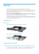
Overview This document is applicable to HP LB module (hereinafter referred to as LB module) The HP LB module are designed for data centers of carriers, portal websites, large and medium-sized enterprises, and industries. The LB module can be installed on an HP 7500/9500/12500 switch or an 8800 router to provide load balancing services.
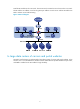
Install the LB module into the core switch. The access switch connects the server cluster to the core switch. The LB module's IP address is used as the gateway IP address on each server and the LB module uses NAT to achieve server load balancing. Figure 3 Network diagram In large data centers of carriers and portal websites Generally, load balancing is implemented in large data centers of carriers and portal websites.
Figure 4 Network diagram 3
Login overview This chapter describes the available login methods and their configuration procedures. Login methods at a glance For the first login, you can connect a terminal to the console port of the LB module to access the CLI or use the username admin and password admin to access the Web interface of the LB module. After login, you can configure other login methods, such as Telnet and SSH for remote access.
Login method Default setting and configuration requirements By default, SNMP login is disabled. To use SNMP service, complete the following configuration tasks: • Assign an IP address to a Layer 3 interface, and make sure the interface and the NMS can reach each other. By default, the LB module has the IP address 192.168.0.1/24 configured for the interface GigabitEthernet 0/1. Logging in through SNMP • Configure SNMP basic parameters.
A relative number uniquely identifies a user interface among all user interfaces that are the same type. The number format is user interface type + number. All user interfaces are numbered starting from 0 and incrementing by 1. For example, the first VTY user interface is VTY 0.
Logging in to the CLI By default, the first time you access the CLI you can log in through the console port. At the CLI, you can configure Telnet or SSH for remote access. Logging in through the console port for the first time To log in through the console port, make sure the console terminal has a terminal emulation program (for example, HyperTerminal in Windows XP). In addition, the port settings of the terminal emulation program must be the same as the default settings of the console port in Table 3.
Figure 6 Connection description Figure 7 Specifying the serial port used to establish the connection 8
Figure 8 Setting the properties of the serial port 5. Power on the LB module and press Enter at the prompt. Figure 9 CLI 6. At the default user view prompt , enter commands to configure the LB module or view the running status of the LB module. To get help, enter ?. Configuring console login control settings The following authentication modes are available for controlling console logins: • None—Requires no authentication. This mode is insecure. • Password—Requires password authentication.
Table 4 Configuration required for different console login authentication modes Authentication mode Configuration tasks Reference None Set the authentication mode to none for the console user interface. "Configuring none authentication for console login" Password Enable password authentication on the console user interface. "Configuring password authentication for console login" Set a password. Enable scheme authentication on the console user interface.
Figure 10 Accessing the CLI through the console port without authentication Configuring password authentication for console login Step Command Remarks 1. Enter system view. system-view N/A 2. Enter console user interface view. user-interface console first-number [ last-number ] N/A 3. Enable password authentication. authentication-mode password By default, you can log in to the LB module through the console port without authentication and have user privilege level 3 after login. 4.
Configuring scheme authentication for console login When scheme authentication is used, you can choose to configure the command authorization and command accounting functions. If command authorization is enabled, a command is available only if the user has the commensurate user privilege level and is authorized to use the command by the AAA scheme. Command accounting allows the HWTACACS server to record all commands executed by users, regardless of command execution results.
Step Command Remarks Optional. 7. Apply an AAA authentication scheme to the intended domain. a. Enter ISP domain view: domain domain-name By default, local authentication is used. b. Apply an AAA scheme to the domain: authentication default { hwtacacs-scheme hwtacacs-scheme-name [ local ] | local | none | radius-scheme radius-scheme-name [ local ] } For local authentication, configure local user accounts. c.
Configuring common console user interface settings (optional) Some common settings configured for a console user interface take effect immediately and can interrupt the console login session. To save you the trouble of repeated re-logins, use a login method different from console login to log in to the LB module before you change console user interface settings.
Step Command Remarks 10. Configure the user privilege level for login users. user privilege level level By default, the default command level is 3 for the console user interface. 11. Set the maximum number of lines to be displayed on a screen. screen-length screen-length 12. Set the size of command history buffer. history-command max-size value 13. Set the idle-timeout timer. idle-timeout minutes [ seconds ] By default, a screen displays 24 lines at most.
• None—Requires no authentication. This mode is insecure. • Password—Requires a password for accessing the CLI. If your password was lost, log in to the LB module through the console port to re-set the password. • Scheme—Uses the AAA module to provide local or remote authentication. You must provide a username and password for accessing the CLI. If the password configured in the local user database was lost, log in to the LB module through the console port and re-set the password.
Step 5. 6. Command Remarks Configure the command level for login users on the current user interfaces. user privilege level level By default, the default command level is 0 for VTY user interfaces. Configure common settings for the VTY user interfaces. See "Configuring common VTY user interface settings (optional)." Optional. The next time you attempt to Telnet to the LB module, you do not need to provide any username or password, as shown in Figure 14.
Step Command Remarks 5. Set a password. set authentication password [ hash ] { cipher | simple } password By default, no password is set. 6. Configure the user privilege level for login users. user privilege level level The default level is 0. 7. Configure common settings for VTY user interfaces. See "Configuring common VTY user interface settings (optional)." Optional. The next time you attempt to Telnet to the LB module, you must provide the configured login password, as shown in Figure 15.
• To make the command authorization or command accounting function take effect, apply an HWTACACS scheme to the intended ISP domain. This scheme must specify the IP address of the authorization server and other authorization parameters. • If the local authentication scheme is used, use the authorization-attribute level level command in local user view to set the user privilege level on the LB module.
Step Command Remarks 10. Set a password. password [ [ hash ] { cipher | simple } password ] By default, no password is set. 11. Specify the command level of the local user. authorization-attribute level level 12. Specify Telnet service for the local user. service-type telnet By default, no service type is specified. 13. Exit to system view. quit N/A 14. Configure common settings for VTY user interfaces. See "Configuring common VTY user interface settings (optional)." Optional. Optional.
Step Command Remarks 1. Enter system view. system-view N/A 2. Enter one or multiple VTY user interface views. user-interface vty first-number [ last-number ] N/A 3. Enable the terminal service. shell 4. Enable the user interfaces to support Telnet, SSH, or both of them. protocol inbound { all | ssh | telnet } 5. Define a shortcut key for terminating tasks. escape-key { default | character } 6. Configure the type of terminal display. terminal type { ansi | vt100 } Optional.
Using the LB module to log in to a Telnet server You can use the LB module as a Telnet client to log in to a Telnet server. If the server is located in a different subnet than the LB module, make sure the two devices have routes to reach each other. Figure 17 Telnetting from the LB module to a Telnet server To use the LB module to log in to a Telnet server: Step Command Remarks system-view N/A 1. Enter system view. 2. Specify the source IPv4 address or source interface for outgoing Telnet packets.
Table 7 SSH server and client requirements Device role Requirements SSH server Assign an IP address to a Layer 3 interface, and make sure the interface and the client can reach each other. By default, the LB module has the IP address 192.168.0.1/24 configured for the interface GigabitEthernet 0/1. Configure the authentication mode and other settings. SSH client If a host operates as an SSH client, run the SSH client program on the host. Obtain the IP address of the Layer 3 interface on the server.
Step Command Remarks By default, scheme authentication is enabled on VTY user interfaces. 5. Enable scheme authentication. authentication-mode scheme 6. Enable the user interfaces to support Telnet, SSH, or both of them. protocol inbound { all | ssh } Optional. By default, both Telnet and SSH are supported. Optional. 7. Enable command authorization. command authorization By default, command authorization is disabled. The commands available for a user only depend on the user privilege level.
Using the LB module to log in to an SSH server You can use the LB module as an SSH client to log in to an SSH server. If the server is located in a different subnet than the LB module, make sure the two devices have routes to reach each other. Figure 19 Logging in to an SSH server from the LB module Perform the following tasks in user view: Task Command Remarks Log in to an IPv4 SSH server. ssh2 server The server argument represents the IPv4 address or host name of the server.
Task Command Remarks Available in user view. Lock the current user interface. lock Send messages to user interfaces. send { all | num1 | { aux | console | vty } num2 } By default, the system does not automatically lock a user interface. 26 Available in user view.
Logging in to the Web interface The device provides Web-based configuration interfaces for visual device management and maintenance. Figure 20 Web-based network management operating environment IP network LB PC Web login guidelines and restrictions • The PC where you configure the device is not necessarily the Web-based network management terminal. A Web-based network management terminal is a PC (or another terminal) used to log in to the Web interface and is required to be reachable to the device.
1. Connect the Ethernet port of the device to the PC by using a crossover Ethernet cable. 2. Configure an IP address for the PC and make sure the PC and the device can reach each other. For example, assign the PC an IP address (for example, 192.168.0.2) within the network segment 192.168.0.0/24 (except for 192.168.0.1). 3. Open the browser and input the login information: a. Type the IP address http://192.168.0.1 in the address bar and press Enter. b.
Table 8 Basic Web login configuration requirements Object Requirements Assign an IP address to a Layer 3 interface. Configure routes to make sure the interface and the PC can reach each other. LB module Perform either or both of the following tasks: • Configuring HTTP login • Configuring HTTPS login Install a Web browser. PC Obtain the IP address of the LB module's Layer 3 interface. Configuring HTTP login Step Command Remarks Optional. 1. Specify a fixed verification code for Web login.
Step Command Remarks password [ [ hash ] { cipher | simple } password ] By default, no password is configured for a newly created local user, and the password for local user admin is admin. 10. Specify the command level of the local user. authorization-attribute level level No command level is configured for the local user. 11. Specify the Telnet service type for the local user. service-type web By default, no service type is configured for the local user. 12. Exit to system view. quit N/A 13.
Step Command Remarks Optional. By default, the HTTPS service is not associated with any SSL server policy, and the LB module uses a self-signed certificate for authentication. 3. Associate the HTTPS service with an SSL server policy. ip https ssl-server-policy policy-name If you disable the HTTPS service, the system automatically de-associates the HTTPS service from the SSL service policy. Before re-enabling the HTTPS service, associate the HTTPS service with an SSL server policy first.
Step 7. Command Associate the HTTPS service with an ACL. Remarks By default, the HTTPS service is not associated with any ACL. ip https acl acl-number Associating the HTTPS service with an ACL enables the LB module to allow only clients permitted by the ACL to log in. Optional. By default, a user must enter the correct username and password to log in through HTTPS. When the auto mode is enabled: • If the user's PKI certificate is correct and 8.
Displaying and maintaining Web login Task Command Remarks Display information about Web users. display web users [ | { begin | exclude | include } regular-expression ] Available in any view. Display HTTP state information. display ip http [ | { begin | exclude | include } regular-expression ] Available in any view. Display HTTPS state information. display ip https [ | { begin | exclude | include } regular-expression ] Available in any view.
Figure 23 Web login page # Enter the user name, password, verify code, and click Login. The homepage appears. After login, you can configure device settings through the Web interface. HTTPS login configuration example Network requirements As shown in Figure 24, to prevent unauthorized users from accessing the LB module, configure the LB module as the HTTPS server and the host as the HTTPS client, and request a certificate for each of them.
Configuration procedure This example assumes that the CA is named new-ca, runs Windows Server, and is installed with the SCEP add-on. This example also assumes that LB, host, and CA can reach one other. 1. Configure LB (HTTPS server): # Configure a PKI entity, configure the common name of the entity as http-server1, and the FQDN of the entity as ssl.security.com. system-view [LB] pki entity en [LB-pki-entity-en] common-name http-server1 [LB-pki-entity-en] fqdn ssl.security.
# Associate the HTTPS service with certificate attribute-based access control policy myacp. [LB] ip https certificate access-control-policy myacp # Enable the HTTPS service. [LB] ip https enable # Create a local user named usera, set the password to 123, specify the Web service type, and specify the user privilege level 3. A level-3 user can perform all operations supported by the LB.
Figure 25 Internet Explorer setting (I) 3. Click Custom Level. The dialog box Security Settings appears. 4. Enable these functions: Run ActiveX controls and plug-ins, script ActiveX controls marked safe for scripting and active scripting.
Figure 26 Internet Explorer Setting (II) 5. Click OK in the Security Settings dialog box. Configuring Firefox Web browser Settings 1. Open the Firefox Web browser, and select Tools > Options. 2. Click the Content tab, select the Enable JavaScript box, and click OK.
Figure 27 Firefox Web browser setting 39
Logging in through SNMP You can run SNMP on an NMS to access the MIB and perform GET and SET operations to manage and monitor the LB module. The LB module supports SNMPv1, SNMPv2c, and SNMPv3, and can work with various network management software modules, including IMC. For more information about SNMP, see System Maintenance Configuration Guide. By default, SNMP access is disabled. To enable SNMP access, log in to the LB module through any other method and configure SNMP login.
Step 3. 4. Command Remarks Configure an SNMP group and specify its access right. snmp-agent group v3 group-name [ authentication | privacy ] [ read-view read-view ] [ write-view write-view ] [ notify-view notify-view ] [ acl acl-number | acl ipv6 ipv6-acl-number ] * By default, no SNMP group is configured. Add a user to the SNMP group.
NMS login example Network requirements Configure the LB module and network management station so you can remotely manage the LB module through SNMPv3. Figure 29 Network diagram Configuration procedure 1. Configure LB: # Assign an IP address to the LB module. Make sure the LB module and the NMS can reach each other. (Details not shown.) # Enter system view. system-view # Enable the SNMP agent. [LB] snmp-agent # Configure an SNMP group.
Logging in to the LB module from the network device Logging in to the LB module from the network device Use the following command to log in to the LB module. After login, the terminal screen displays the CLI of the LB module. To return to the CLI on the device, press Ctrl+K. To log in to the LB module from the network device, execute one of the following commands in user view as appropriate: Task Command • In standalone mode: oap connect slot slot-number Log in to the OAP system from the device.
Configuring a management IP address for the LB module NOTE: Support for this feature varies by the device model and software release of the network device that holds the LB module. In the OAA system, the network device and the LB module integrate together and function as one device. For the SNMP UDP domain-based NMS, however, the device and the LB module are independent SNMP agents. Physically, the two agents are on the same managed object.
An ACSEI server supports multiple ACSEI clients. ACSEI timers An ACSEI server uses two timers, which can be set at the CLI: • Clock synchronization timer—Used to periodically trigger the ACSEI server to send clock synchronization advertisements to the ACSEI clients. • Client monitoring timer—Used to periodically trigger the ACSEI server to send monitoring requests to the ACSEI clients.
To configure the ACSEI client on the LB module: Step Command Remarks 1. Enter system view. system-view N/A 2. Enter interface view. interface interface-type interface-number N/A 3. Enable ACSEI client. acsei-client enable Disabled by default. Displaying and maintaining ACSEI server and client Task Command Remarks Display ACSEI client summary on the ACSEI server. display acsei client summary [ client-id ] [ | { begin | exclude | include } regular-expression ] Available in any view.
Configuration procedure The following configuration uses a switch as an example. The configuration on a router is the same. 1. Log in to the LB module from the network device. oap connect slot 3 Connected to OAP! 2. Configure the clock synchronization timer and the monitoring timer on the network device: # Enable ACSEI server. system-view [Switch] acsei server enable # Enter ACSEI server view.
Displaying device information When you log in to the Web interface, you are placed on the Summary > Device Info page.
Select the refresh mode from the Refresh Period list. • If you select a specific period, the system periodically refreshes the Device Info page. • If you select Manual, click Refresh to refresh the page. Displaying device information Table 9 Field description Field Description Device Location Location of the device. Contact Information Contact information for device maintenance. SerialNum Serial number of the device. Software Version Software version of the device.
Field Description Interface status: Status • • • —The interface is up and is connected. —The interface is up, but not connected. —The interface is down. To know more information about device interfaces, click the More hyperlink under the Device Interface Information area to enter the System > Interface page to view and operate the interfaces. For more information, see Network Management Configuration Guide.
Managing the device Device management includes monitoring the operating status of devices and configuring their running parameters. The configuration tasks in this document are order independent. You can perform these tasks in any order. Configuring the device name A device name identifies a device in a network and works as the user view prompt at the CLI. For example, if the device name is Sysname, the user view prompt is . Configuring the device name in the Web interface 1.
Changing the system time You must synchronize your device with a trusted time source by using NTP or changing the system time before you run it on the network. Network management depends on an accurate system time setting, because the timestamps of system messages and logs use the system time. For NTP configuration, see "Configuring NTP." In a small-sized network, you can manually set the system time of each device.
Figure 35 Calendar page 3. Modify the system time either in the System Time Configuration text box, or through the calendar page. You can perform the following operations on the calendar page: { { 4. Click Today to set the current date on the calendar to the current system date of the local host, and the time stays unchanged. Set the year, month, date and time, and then click OK. Click Apply in the system time configuration page to save your configuration.
Item Description Adjust the system clock for daylight saving time changes, which means adding one hour to the current system time. Click Adjust clock for daylight saving time changes to expand the option, as shown in Figure 37. You can configure the daylight saving time changes in the following ways: Adjust clock for daylight saving time changes • Specify that the daylight saving time starts on a specific date and ends on a specific date.
Command Effective system time The original system time outside the daylight saving time range: The system time does not change until it falls into the daylight saving time range. Configuration example System time clock summer-time ss one-off 1:00 2012/1/1 1:00 2012/8/8 2 01:00:00 UTC Sat 01/01/2012. 03:00:00 ss Sat 01/01/2012. 3 The original system time in the daylight saving time range: The system time increases by summer-offset.
Command Effective system time Configuration example Original system clock ± zone-offset outside the daylight saving time range: Original system clock ± zone-offset 2, 3 or 3, 2 Original system clock ± zone-offset outside the daylight saving time range: Original system clock ± zone-offset + summer-offset clock timezone zone-time add 1 clock summer-time ss one-off 1:00 2012/1/1 1:00 2012/8/8 2 clock timezone zone-time add 1 clock summer-time ss one-off 1:00 2012/1/1 1:00 2012/8/8 2 System time 02:00:0
Configuration procedure To change the system time: Step Command 1. Set the system time and date. clock datetime time date 2. Enter system view. system-view Set the time zone. clock timezone zone-name { add | minus } zone-offset 3. Remarks Optional. Available in user view. N/A Optional. Coordinated UTC time zone by default. • Set a non-recurring scheme: 4. Set a daylight saving time scheme.
To set the idle timeout timer: Step Command Remarks 1. Enter system view. system-view N/A 2. Enter user interface view. user-interface { first-num1 [ last-num1 ] | { aux | console | vty } first-num2 [ last-num2 ] } N/A 3. Set the Web idle timeout timer. idle-timeout minutes [ seconds ] 10 minutes by default. Enabling displaying the copyright statement The device by default displays the copyright statement when a Telnet or SSH user logs in, or when a console user quits user view.
keywords and the delimiters cannot exceed 510 characters. In this mode, do not press Enter before you input the end delimiter. For example, you can configure the shell banner "Have a nice day." as follows: system-view [System] header shell %Have a nice day.% Multiple-line input • Input message text in multiple lines. In this approach, the message text can be up to 2000 characters.
Configuring the maximum number of concurrent users You can configure this command to limit the number of users that can enter the system view simultaneously. When the number of concurrent users reaches the upper limit, other users cannot enter system view. When multiple users configure a setting in system view, only the last configuration applies. To configure the maximum number of concurrent users: Step Command Remarks 1. Enter system view. system-view N/A 2.
Power off and then power on the device. This method might cause data loss, and is the least-preferred method. • Reboot in the Web interface or at the CLI enables easy remote device maintenance. Rebooting the device in the Web interface 1. Select System > Reboot from the navigation tree. Figure 39 Rebooting the device 2. If necessary, select Check whether the configuration is saved to the configuration file for next reboot. { { 3.
Task Command Remarks • Schedule a reboot to occur at a specific time and date: schedule reboot at hh:mm [ date ] Schedule a reboot. • Schedule a reboot to occur Use either command. The scheduled reboot function is disabled by default. after a delay: schedule reboot delay { hh:mm | mm } Changing any clock setting can cancel the reboot schedule. Scheduling jobs You can schedule a job to automatically run a command or a set of commands without administrative interference.
Configuration guidelines • To have a job successfully run a command, make sure the specified view and command are valid. The system does not verify their validity. • After job execution, the configuration interface, view, and user status that you have before job execution restores even if the job ran a command to change the user interface (for example, telnet, ftp, and ssh2), the view (for example, system-view and quit), or the user status (for example, super).
Step Command Remarks • Configure a command to run at a specific time and date: time time-id at time date command command • Configure a command to run at a 4. Add commands to the job. specific time: time time-id { one-off | repeating } at time [ month-date month-day | week-day week-daylist ] command command Use any of the commands. Changing a clock setting does not affect the schedule set by using the time at or time delay command.
[LB-job-pc1] quit # Create a job named pc2, and enter its view. [LB] job pc2 # Configure the job to be executed in the view of GigabitEthernet 0/2. [LB-job-pc2] view gigabitethernet 0/2 # Configure the LB module to enable GigabitEthernet 0/2 at 8:00 on working days every week. [LB-job-pc2] time 1 repeating at 8:00 week-day mon tue wed thu fri command undo shutdown # Configure the LB module to shut down GigabitEthernet 0/2 at 18:00 on working days every week.
Step Command Remarks 1. Enter system view. system-view N/A 2. Configure the temperature threshold for a device. temperature-limit slot slot-number hotspot sensor-number lowerlimit warninglimit Optional. Clearing unused 16-bit interface indexes The device must maintain persistent 16-bit interface indexes and keep one interface index match one interface name for network management.
Diagnosing transceiver modules The device provides the alarm function and digital diagnosis function for transceiver modules. When a transceiver module fails or works inappropriately, you can examine the alarms present on the transceiver module to identify the fault source or examine the key parameters monitored by the digital diagnosis function, including the temperature, voltage, laser bias current, TX power, and RX power. To diagnose transceiver modules: Step Command Remarks 1.
Task Command Remarks Display CPU usage statistics. display cpu-usage [ entry-number [ offset ] [ verbose ] [ from-device ] ] [ | { begin | exclude | include } regular-expression ] Available in any view. Display historical CPU usage statistics in charts. display cpu-usage history [ task task-id ] [ | { begin | exclude | include } regular-expression ] Available in any view. Display device information.
Configuring local users Local users are a set of user attributes configured on the local device. A local user is uniquely identified by username. To enable users using a certain network service to pass the local authentication, you must configure accounts for the users to the local user database on the device.
Configuring a user privilege level for users through the AAA module Step Command Remarks 1. Enter system view. system-view N/A 2. Enter user interface view. user-interface { first-num1 [ last-num1 ] | { aux | console | vty } first-num2 [ last-num2 ] } Only LB cards support AUX user interfaces. 3. Specify the scheme authentication mode. authentication-mode scheme By default, the authentication mode is scheme for VTY users and none for console and AUX users. 4. Return to system view.
Configuring the user privilege level directly on a user interface To configure the user privilege level directly on a user interface that uses the scheme authentication mode: Step Command Remarks 1. Configure the authentication type for SSH users as publickey. For more information, see Security Configuration Guide. Required only for SSH users who use public-key authentication. 2. Enter system view. system-view N/A 3. Enter user interface view.
# Configure the device to perform no authentication for Telnet users, and to authorize authenticated Telnet users to use level-0 and level-1 commands. (Use no authentication mode only in a secure network environment.) system-view [Sysname] user-interface vty 0 4 [Sysname-ui-vty0-4] authentication-mode none [Sysname-ui-vty0-4] user privilege level 1 # Display the commands a Telnet user can use after login. Because the user privilege level is 1, a Telnet user can use more commands now.
When administrators must leave for a while or ask someone else to manage the device temporarily, they can switch to a lower privilege level before they leave to restrict the operation by others. Configuring the authentication parameters for user privilege level switching A user can switch to a lower privilege level without authentication. To switch to a higher privilege level, however, a user must provide the privilege level switching authentication information (if any).
Step Command Remarks If local authentication is involved, this step is required. 3. Configure the password for the user privilege level. super password [ level user-level ] { cipher | simple } password By default, a privilege level has no password. If no user privilege level is specified when you configure the command, the user privilege level defaults to 3.
User interface authentication mode User privilege level switching authentication mode Information required for the first authentication mode Information required for the second authentication mode local scheme Password configured for the privilege level on the device with the super password command. Password for privilege level switching configured on the AAA server. The system uses the login username as the privilege level switching username.
Figure 42 Adding a local user 3. Configure a local user, as described in Table 18. 4. Click Apply. Table 18 Configuration items Item Description Enter the username of the local user. User Name The username can contain spaces in the middle. However, the device ignores any leading spaces in the username. Set the user privilege level of a user. User Privilege Level User privilege levels are visitor, monitor, configure, and management in ascending order.
Item Description Set the virtual device to which a user belongs. Virtual Device Every time a user logs in through the Web interface, the user logs in to the virtual device to which the user belongs. When a root virtual device user with privilege level Configure or Management logs in to the device, the user can log in to another virtual device by selecting System > Device > Virtual Device > Virtual Device.
Figure 44 Creating a local user c. Enter Emily as the username. d. Select the user privilege level Monitor. e. Select the service type Web. f. Enter aabbcc as the password and confirm the password. g. Select the password encryption method Reversible. h. Select the virtual device Root. i. Click Apply. Configuring local users at the CLI See the chapter on AAA in Security Configuration Guide.
Controlling user logins User login control can be configured only at the CLI. Use ACLs to prevent unauthorized logins. For more information about ACLs, see Security Configuration Guide. Controlling Telnet logins Use a basic ACL (2000 to 2999) to filter Telnet traffic by source IP address. Use an advanced ACL (3000 to 3999) to filter Telnet traffic by source and/or destination IP address. Use an Ethernet frame header ACL (4000 to 4999) to filter Telnet traffic by source MAC address.
Configuring source/destination IP-based Telnet login control Step Command Remarks 1. Enter system view. system-view N/A 2. Create an advanced ACL and enter its view, or enter the view of an existing advanced ACL. acl [ ipv6 ] number acl-number [ name name ] [ match-order { config | auto } ] By default, no advanced ACL exists. 3. Configure an ACL rule. rule [ rule-id ] { permit | deny } rule-string N/A 4. Exit advanced ACL view. quit N/A 5. Enter user interface view.
Figure 45 Network diagram Host A 10.110.100.46 IP network LB Host B 10.110.100.52 Configuration procedure # Configure basic ACL 2000, and configure rule 1 to permit packets sourced from Host B, and rule 2 to permit packets sourced from Host A. system-view [LB] acl number 2000 match-order config [LB-acl-basic-2000] rule 1 permit source 10.110.100.52 0 [LB-acl-basic-2000] rule 2 permit source 10.110.100.
Step Command Remarks • SNMPv1/v2c community: snmp-agent community { read | write } community-name [ mib-view view-name ] [ acl acl-number | acl ipv6 ipv6-acl-number ] * • SNMPv1/v2c group: snmp-agent group { v1 | v2c } group-name [ read-view read-view ] [ write-view write-view ] [ notify-view notify-view ] [ acl acl-number | acl ipv6 ipv6-acl-number ] * • SNMPv3 group: 5. Apply the ACL to an SNMP community, group, or user.
[LB] acl number 2000 match-order config [LB-acl-basic-2000] rule 1 permit source 10.110.100.52 0 [LB-acl-basic-2000] rule 2 permit source 10.110.100.46 0 [LB-acl-basic-2000] quit # Associate the ACL with the SNMP community and the SNMP group.
Web login control configuration example Network requirements Configure the LB module in Figure 47 to provide Web access service only to Host B. Figure 47 Network diagram Host A 10.110.100.46 IP network LB Host B 10.110.100.52 Configuration procedure # Create ACL 2030, and configure rule 1 to permit packets sourced from Host B. system-view [LB] acl number 2030 match-order config [LB-acl-basic-2030] rule 1 permit source 10.110.100.
Field User Type Description Access type of the online user, such as Admin (Telnet or Web). The Web page does not display FTP users. Login Time User login time. Online Duration Elapsed time after user login.
Configuring VDs Overview The virtualization technology can virtualize a physical device into multiple logical devices called "virtual devices (VDs)." All VDs share the hardware and software resources of the physical device, but each VD has its own Layer 3 interfaces, maintains its own routing and forwarding entries, serves its own users, and has its own administrators. Creating, running, or deleting a VD does not affect the configuration or service of any other VD.
Figure 50 Network diagram Default VD and non-default VDs A device supporting VDs is a VD itself, and it is called the "default VD" (for example, Device in Figure 50). The default VD always uses the name Root and the ID 1. You cannot delete it or change its name or ID. From the default VD, you can manage the whole physical device, create and delete non-default VDs, and assign interface and VLAN resources to non-default VDs. No VDs can be created on a non-default VD.
Step Description Optional. 3. Assigning VLANs to a VD By default, all VLANs belong to the root VD, and the other VDs have no VLAN to use. A VLAN can belong to only one VD at a time. Optional. 4. Logging in to a VD A user who has the configuration or management privilege level on the root VD can log in to another VD to perform the same operations as the VD's users of the same operation level. Creating a VD 1.
Table 20 Configuration items Item Description Virtual Device ID Enter a VD ID that is globally unique. Virtual Device Name Enter a VD name that is globally unique. Set the maximum number of concurrent sessions that can be established on the VD. Max. Sessions Limiting the maximum number of concurrent sessions helps protect the device against potential attacks, such as SYN flood attacks. Max.
Assigning VLANs to a VD 1. Select System > Device Management > Virtual Device > VLAN from the navigation tree. A list appears, showing the VDs and the VLANs. Figure 54 Assigning VLANs to a VD 2. Click the icon in the Operation column of a VD. 3. Enter the VLAN range for the VD in the VLAN Range column. 4. Click Apply. Logging in to a VD To log in to a VD, log in to the device, and then complete the following steps: 1.
Figure 56 Network diagram Configuration procedure 1. Create VD VD_A: a. Select System > Device Management > Virtual Device > Configuration from the navigation tree. b. Click Add. The page for adding a VD appears. Figure 57 Creating VD_A c. Enter the VD ID 2. d. Enter the VD name VD_A. e. Set the maximum number of sessions to 100000. f. Set the maximum number of real service groups for load balancing to 100. g. Set the maximum number of real services for load balancing to 200. h.
Figure 58 Creating VD_B b. Enter the VD ID 3. c. Enter the VD name VD_B. d. Set the maximum number of sessions to 100000. e. Set the maximum number of real service groups for load balancing to 0. f. Set the maximum number of real services for load balancing to 0. g. Set the maximum number of virtual services for load balancing to 0. h. Click Apply. 3. Assign interfaces to the VDs: a. Select System > Device Management > Virtual Device > Interface from the navigation tree. b.
Figure 60 Assigning VLANs to VD_A 5. Assign VLANs to VD_B: a. Select System > Device Management > Virtual Device > VLAN from the navigation tree. b. Click the c. icon for VD_B, and enter VLAN ranges 50-80,400,500-530. Click Apply. Figure 61 Assigning VLANs to VD_B Creating a VD at the CLI VD configuration task list Task Remarks Creating a VD Required. Assigning resources to a VD Assigning a Layer 3 interface to a VD Required. Assigning a VLAN to a VD Optional.
To enter the view of an existing VD, you can specify the VD name, or specify both the VD name and the VD ID. If you specify both the VD name and the VD ID, make sure the two arguments identify the same VD. To create a VD: Step Command Remarks 1. Enter system view. system-view N/A 2. Create a VD and enter VD view. vd vd-name id vd-id By default, there is a default VD with the name Root and the ID 1.
A VLAN can be assigned to only one VD. Assigning a VLAN to a second VD is the same as reclaiming the VLAN and assigning it to the second VD. Setting the maximum number of sessions for a VD You can put a limit on the maximum of sessions that can be set up on a VD. The actual number of sessions available for a VD, however, is also restricted by the number of sessions available on the physical device. To set the maximum number of sessions for a VD: Step Command Remarks 1. Enter system view.
Step 2. 3. Log in to the VD. Set the maximum number of concurrent sessions for the VD. Command Remarks switchto vd vd-name Optional. session max-entries max-entries By default, the maximum number of concurrent sessions for a non-default VD equals the maximum number of sessions specified for the VD by using the limit-resource session max-entries command.
[LB] vd vdb id 3 # Assign interface GigabitEthernet 0/2 to VD vdb. [LB-vd-vdb] allocate interface gigabitethernet 0/2 # Assign VLAN 50 to VLAN 80, VLAN 400, and VLAN 500 to VLAN 530 to VD vdb. [LB-vd-vdb] allocate vlan 50 to 80 400 500 to 530 # Set the maximum number of sessions to 200000 for VD vdb. [LB-vd-vdb] limit-resource session max-entries 200000 Verifying the configuration Administrators of enterprise A can log in to VD vda, and administrators of enterprise B can log in to VD vdb.
Configuring unified multisystem management Overview You can install a LB module into a device to offload the load balancing service from the device. This module has an independent operating system. Unified multisystem management enables you to configure LB modules in the device's Web interface. To implement unified multisystem management, configure the device as the ACSEI server and the LB module as the ACSEI client.
Step Enter system view. 1. Command Remarks system-view N/A By default, no unified management VLAN is configured. 2. Configure the unified management VLAN. unified-management vlan vlan-id 3. Enter the view of the interface connected to the device. interface interface-type interface-number N/A 4. Enable the ACSEI client. acsei-client enable By default, the ACSEI client is disabled. The unified management VLAN is used to forward management packets among multiple systems.
2. Configure the LB module: # Configure the unified management VLAN. system-view [LB] unified-management vlan 3000 # Enable ACSEI client. [LB] interface ten-gigabitethernet 0/0 [LB-Ten-GigabitEthernet0/0] acsei-client enable [LB-Ten-GigabitEthernet0/0] quit # Configure the local user to log in to the Web interface. [LB] local-user admin [LB-luser-admin] password simple admin [LB-luser-admin] authorization-attribute level 3 [LB-luser-admin] service-type web Verifying the configuration 1.
Configuring NTP You must synchronize your device with a trusted time source by using the Network Time Protocol (NTP) or changing the system time before you run it on a live network. Various tasks, including network management, charging, auditing, and distributed computing depend on an accurate system time setting, because the timestamps of system messages and logs use the system time. Overview NTP is typically used in large networks to dynamically synchronize time among network devices.
• Prior to the time synchronization, the time of Device A is set to 10:00:00 am and that of Device B is set to 11:00:00 am. • Device B is used as the NTP server. Device A is to be synchronized to Device B. • It takes 1 second for an NTP message to travel from Device A to Device B, and from Device B to Device A. Figure 67 Basic work flow of NTP The synchronization process is as follows: • Device A sends Device B an NTP message, which is timestamped when it leaves Device A.
NTP uses two types of messages: clock synchronization messages and NTP control messages. NTP control messages are used in environments where network management is needed. Because NTP control messages are not essential for clock synchronization, they are not described in this document. A clock synchronization message is encapsulated in a UDP message, as shown in Figure 68. Figure 68 Clock synchronization message format The main fields are described as follows: • LI (Leap Indicator)—A 2-bit leap indicator.
• Precision—An 8-bit signed integer that indicates the precision of the local clock. • Root Delay—Roundtrip delay to the primary reference source. • Root Dispersion—The maximum error of the local clock relative to the primary reference source. • Reference Identifier—Identifier of the particular reference source. • Reference Timestamp—The local time at which the local clock was set or corrected most recently.
Symmetric peers mode Figure 70 Symmetric peers mode In symmetric peers mode, devices that operate in symmetric active mode and symmetric passive mode exchange NTP messages with the Mode field 3 (client mode) and 4 (server mode). Then the device that operates in symmetric active mode periodically sends clock synchronization messages, with the Mode field in the messages set to 1 (symmetric active).
Multicast mode Figure 72 Multicast mode In multicast mode, a server periodically sends clock synchronization messages to the user-configured multicast address, or, if no multicast address is configured, to the default NTP multicast address 224.0.1.1, with the Mode field in the messages set to 5 (multicast mode). Clients listen to the multicast messages from servers.
Figure 73 Configuring the network time 3. Configure the network time as described in Table 21. 4. Click Apply. Table 21 Configuration items Item Description Clock status Display the synchronization status of the system clock. Set the IP address of the local clock source to 127.127.1.u, where the value range for u is 0 to 3, representing the NTP process ID.
Item Description Set NTP authentication key. The NTP authentication feature should be enabled for a system running NTP in a network where there is a high security demand. This feature enhances the network security by means of client-server key authentication, which prohibits a client from synchronizing with a device that has failed authentication. Key 1 You can set two authentication keys, each of which is composed of a key ID and key string. Key 2 • ID is the ID of a key.
Figure 75 Configuring the local clock as the reference clock 3. Configure Device B: Configure Device A as the NTP server of Device B. a. Select System > System Time from the navigation tree. b. Click Network Time Protocol. The page for setting up NTP appears. c. Enter 1.0.1.11 in the NTP Server 1 box. d. Click Apply. Figure 76 Configuring Device A as the NTP server of Device B 4.
After the configuration, you can see that the current system time displayed on the System Time page is the same for Device A and Device B. Configuring NTP at the CLI NTP configuration task list Task Remarks Configuring NTP operation modes Required. Configuring the local clock as a reference source Optional. Configuring optional parameters for NTP Optional. Configuring access-control rights Optional. Configuring NTP authentication Optional.
• For devices operating in symmetric mode, specify a symmetric-passive peer on a symmetric-active peer. • Use the ntp-service refclock-master command or any NTP configuration command in Configuring NTP operation modes to enable NTP. Otherwise, a symmetric-passive peer does not process NTP messages from a symmetric-active peer. • Either the symmetric-active peer or the symmetric-passive peer must be in synchronized state. Otherwise, clock synchronization does not proceed.
Step Command Remarks 2. Enter interface view. interface interface-type interface-number This command enters the view of the interface for sending NTP broadcast messages. 3. Configure the device to operate in NTP broadcast server mode. ntp-service broadcast-server [ authentication-keyid keyid | version number ] * A broadcast server can synchronize broadcast clients only when its clock has been synchronized.
Typically, the stratum level of the NTP server that is synchronized from an authoritative clock (such as an atomic clock) is set to 1. This NTP server operates as the primary reference source on the network, and other devices synchronize to it. The number of NTP hops that devices in a network are away from the primary reference source determines the stratum levels of the devices.
To disable an interface from receiving NTP messages: Step Command Remarks 1. Enter system view. system-view N/A 2. Enter interface view. interface interface-type interface-number N/A 3. Disable the interface from receiving NTP messages. ntp-service in-interface disable By default, an interface is enabled to receive NTP messages. Configuring the allowed maximum number of dynamic sessions NTP has the following types of associations: • Static association—A manually created association.
• Synchronization—Server access only. This level of right permits a peer device to synchronize its clock to that of the local device but does not permit the peer devices to perform control query. • Server—Server access and query permitted. This level of right permits the peer devices to perform synchronization and control query to the local device but does not permit the local device to synchronize its clock to that of a peer device. • Peer—Full access.
On the client, if NTP authentication is enabled and a key is specified to associate with the NTP server, but the key is not a trusted key, the client does not synchronize to the server no matter whether NTP authentication is enabled or not on the server. • To configure NTP authentication for a client: Step Command Remarks 1. Enter system view. system-view N/A 2. Enable NTP authentication. ntp-service authentication enable By default, NTP authentication is disabled.
When the active peer has a smaller stratum level than the passive peer: • On the active peer, if NTP authentication is not enabled, no key is specified to associate with the passive peer, or the key is not a trusted key, the active peer can synchronize to the passive peer as long as NTP authentication is disabled on the passive peer. To configure NTP authentication for an active peer: Step Command Remarks 1. Enter system view. system-view N/A 2. Enable NTP authentication.
Step Command Remarks 1. Enter system view. system-view N/A 2. Enable NTP authentication. ntp-service authentication enable By default, NTP authentication is disabled. 3. Configure an NTP authentication key. ntp-service authentication-keyid keyid authentication-mode md5 [ cipher | simple ] value Configure the key as a trusted key. ntp-service reliable authentication-keyid keyid 4. By default, no NTP authentication key is configured.
Step 3. 4. Command Configure an NTP authentication key. ntp-service authentication-keyid keyid authentication-mode md5 [ cipher | simple ] value Configure the key as a trusted key. ntp-service reliable authentication-keyid keyid Remarks By default, no NTP authentication key is configured. Configure the same authentication key on the client and server. By default, no authentication key is configured to be trusted. To configure NTP authentication for a multicast server: Step Command Remarks 1.
Network requirements Perform the following configurations to synchronize the time between Device B and Device A: • As shown in Figure 77, the local clock of Device A is to be used as a reference source, with the stratum level 2. • Device B operates in client/server mode and Device A is to be used as the NTP server of Device B. Figure 77 Network diagram Configuration procedure • Set the IP address for each interface as shown in Figure 77. (Details not shown.
Reference time: 14:53:27.371 UTC Sep 19 2012 (C6D94F67.5EF9DB22) The output shows that Device B has synchronized to Device A. The stratum level of Device B is 3, and that of Device A is 2. # Display NTP session information for Device B, which shows that an association has been set up between Device B and Device A. [DeviceB] display ntp-service sessions source reference stra reach poll now offset delay disper ************************************************************************** [12345] 1.0.1.
system-view [LBB] ntp-service unicast-server 3.0.1.31 • Configure LB C (after LB B is synchronized to LB A): # Specify the local clock as the reference source, with the stratum level 1. system-view [LBC] ntp-service refclock-master 1 # Configure LB B as a symmetric peer after local synchronization. [LBC] ntp-service unicast-peer 3.0.1.32 In the step above, LB B and LB C are configured as symmetric peers, with LB C in the symmetric-active mode and LB B in the symmetric-passive mode.
Figure 79 Network diagram GE0/1 3.0.1.31/24 LB C NTP broadcast server GE0/1 3.0.1.30/24 LB A NTP broadcast client GE0/1 3.0.1.32/24 LB B NTP broadcast client Configuration procedure • Set the IP address for each interface as shown in Figure 79. (Details not shown.) • Configure LB C: # Specify the local clock as the reference source, with the stratum level 2.
Clock precision: 2^7 Clock offset: 0.0000 ms Root delay: 31.00 ms Root dispersion: 8.31 ms Peer dispersion: 34.30 ms Reference time: 16:01:51.713 UTC Sep 19 2012 (C6D95F6F.B6872B02) The output shows that LB A has synchronized to LB C. The stratum level of LB A is 3, and that of LB C is 2. # Display NTP session information for LB A, which shows that an association has been set up between LB A and LB C.
system-view [LBB] ntp-service refclock-master 2 # Configure LB B to operate in multicast server mode and send multicast messages through GigabitEthernet 0/1. [LBB] interface gigabitethernet 0/1 [LBB-GigabitEthernet0/1] ntp-service multicast-server • Configure LB C: # Configure LB C to operate in multicast client mode and receive multicast messages on GigabitEthernet 0/1.
[Device] interface gigabitethernet 0/2 [Device-GigabitEthernet0/2] pim dm • Configure LB A: system-view [LBA] interface gigabitethernet 0/1 # Configure LB A to operate in multicast client mode and receive multicast messages on GigabitEthernet 0/1. [LBA-GigabitEthernet0/1] ntp-service multicast-client # Display the NTP status of LB A after clock synchronization. [LBA-GigabitEthernet0/1] display ntp-service status Clock status: synchronized Clock stratum: 3 Reference clock ID: 3.0.1.
Figure 81 Network diagram Configuration procedure • Set the IP address for each interface as shown in Figure 81. (Details not shown.) • Configure Device A: # Specify the local clock as the reference source, with the stratum level 2. system-view [DeviceA] ntp-service refclock-master 2 • Configure Device B: system-view # Enable NTP authentication on Device B. [DeviceB] ntp-service authentication enable # Set an authentication key.
# Display NTP session information for Device B, which shows that an association has been set up between Device B and Device A. [DeviceB] display ntp-service sessions source reference stra reach poll now offset delay disper ************************************************************************** [12345] 1.0.1.11 127.127.1.0 2 63 64 3 -75.5 31.0 16.
# Enable NTP authentication on LB B. Configure an NTP authentication key, with the key ID of 88 and key value of 123456. Specify the key as a trusted key. system-view [LBB] ntp-service authentication enable [LBB] ntp-service authentication-keyid 88 authentication-mode md5 123456 [LBB] ntp-service reliable authentication-keyid 88 # Configure LB B to operate in broadcast client mode and receive NTP broadcast messages on GigabitEthernet 0/1.
Clock stratum: 16 Reference clock ID: none Nominal frequency: 100.0000 Hz Actual frequency: 100.0000 Hz Clock precision: 2^18 Clock offset: 0.0000 ms Root delay: 0.00 ms Root dispersion: 0.00 ms Peer dispersion: 0.00 ms Reference time: 00:00:00.000 UTC Jan 1 1900(00000000.00000000) # Enable NTP authentication on LB C. Configure an NTP authentication key, with the key ID of 88 and key value of 123456. Specify the key as a trusted key.
Nominal frequency: 64.0000 Hz Actual frequency: 64.0000 Hz Clock precision: 2^7 Clock offset: 0.0000 ms Root delay: 31.00 ms Root dispersion: 8.31 ms Peer dispersion: 34.30 ms Reference time: 16:01:51.713 UTC Sep 19 2012 (C6D95F6F.B6872B02) Configuration guidelines A device can act as a server to synchronize the clock of other devices only after its clock has been synchronized.
Upgrading software You can use the CLI, Boot menu, or Web interface to upgrade software. This chapter describes how to upgrade software from the CLI and Web. Overview Upgrading software includes upgrading the BootWare (called "bootrom" in CLI) and system software.
Upgrading method Software types Installing hotfixes System software images Remarks Hotfixes repair software defects without requiring a reboot or service interruption. Hotfixes do not add new features to system software images. Upgrading from the Web interface System software images It is a user-friendly method for upgrading the system software image. Upgrading from the Boot menu • BootWare image • System software Use this method when the device cannot start up correctly.
Upgrading system software in the Web interface IMPORTANT: Upgrading software takes some time. During software upgrade, do not perform any operation on the Web interface. Otherwise, the upgrade might be disrupted. To upgrade software: 1. Select System > Software Upgrade from the navigation tree. Figure 84 Software upgrade configuration page 2. Configure upgrade parameters as described in Table 22. 3. Click Apply.
Upgrading system software at the CLI Step 1. 2. 3. Command Remarks The image file must be saved in the root directory for a successful upgrade. Use FTP or TFTP to transfer the system software image to the root directory of the device's storage medium. See System Maintenance Configuration Guide. Specify the file as the startup system software image in user view. boot-loader file file-url { main | backup } N/A Reboot the device.
Patch states A patch is in IDLE, DEACTIVE, ACTIVE, or RUNNING state, depending on the patch manipulation command. Patch manipulation commands include patch load (load), patch active (run temporarily), patch run (confirm running), patch deactive (stop running), patch delete (delete), patch install (install), and undo patch install (uninstall). For example, if you execute the patch active command, patches in DEACTIVE state change to the ACTIVE state.
Figure 86 Patches that are not loaded to the patch memory area DEACTIVE state Patches in DEACTIVE state have been loaded to the patch memory area but have not yet run in the system. Suppose that the patch file you are loading has seven patches. After the seven patches successfully pass the version check and CRC check, they are loaded to the patch memory area and are in DEACTIVE state. In the patch memory area, patch states are as shown in Figure 87.
Figure 88 Patches are activated RUNNING state After you confirm ACTIVE patches, their states change to RUNNING and persist after a reboot. In contrast to ACTIVE patches, RUNNING patches continue to take effect after a reboot. For example, if you confirm the first three patches in Figure 88, their state changes from ACTIVE to RUNNING, and the RUNNING state persists after a reboot. The patch states of the system are shown in Figure 89.
• Save patch files or patch package files to the root directory of the device's storage medium. If the storage medium has been partitioned, save the files to the root directory of the first partition. • Correctly name a patch file in the patch_PATCH-FlAG suffix.bin format. The PATCH-FLAG suffix is predefined and must be the same as the first three characters of the value for the Version field in the output from the display patch information command.
Task Remarks Confirming ACTIVE patches Optional. Configuring the patch file location For reliable patch loading, HP recommends saving patch files to the root directory of the storage medium. If the patch file is saved in the root directory, you do not need to specify the patch location. If not, use the patch location patch-location command to specify the patch file location. To configure the patch file location: Step Command Remarks 1. Enter system view. system-view N/A 2.
Step 2. Command Activate patches. patch active [ patch-number ] Confirming ACTIVE patches To have an ACTIVE patch continue to run after a reboot, perform the task in this section. After you confirm an ACTIVE patch, its state changes to RUNNING and persists after a reboot. To confirm ACTIVE patches: Step Command 1. Enter system view. system-view 2. Confirm ACTIVE patches.
Task Command Remarks Display information about the patch package. display patch [ | { begin | exclude | include } regular-expression ] Available in any view. Display patch information. display patch information [ | { begin | exclude | include } regular-expression ] Available in any view. Software upgrade examples Upgrading the entire system software from the CLI Network requirement The current system software version is soft-version1 for the LB module in Figure 90.
ftp 2.2.2.2 Trying 2.2.2.2 ... Press CTRL+K to abort Connected to 2.2.2.2. 220 WFTPD 2.0 service (by Texas Imperial Software) ready for new user User(2.2.2.2:(none)):aaa 331 Give me your password, please Password: 230 Logged in successfully # Download new-config.cfg from the FTP server. [ftp] ascii [ftp] get new-config.cfg # Download soft-version2.bin from the FTP server. [ftp] binary [ftp] get soft-version2.bin [ftp] bye # Specify new-config.cfg as the next-startup configuration file.
# Use the save command to save the running configuration. (Details not shown.) # Examine the storage medium on the LB module for space insufficiency. If the free space is not sufficient for the patches, delete unused files. (Details not shown.) # Download patch_hfw.bin from the TFTP server to the root directory of the LB module's storage medium. tftp 2.2.2.2 get patch_hfw.bin # Install the patches. system-view [LB] patch install cfa0: Patches will be installed.
Managing configuration files You can use the CLI, Boot menu, or Web interface to manage configuration files. This chapter describes the CLI and Web interface approaches to configuration file management. Overview A configuration file saves configurations as a set of text commands. You can save the running configuration to a configuration file so the configuration takes effect after you reboot the device. You can also back up the configuration file on to a host and download the file to the device as needed.
Configuration file content organization and format IMPORTANT: To run on the device, a configuration file must meet the content and format requirements of the device. To avoid any configuration loading problem at startup, use a configuration file created on the device. If you edit the configuration file, make sure all edits are compliant with the requirements of the device. A configuration file must meet the following requirements: • All commands are saved in their complete form.
Figure 92 Saving the configuration To save the configuration in common mode: 1. Select System > Maintenance from the navigation tree. The Save page appears, as shown in Figure 92. 2. To encrypt the configuration file, select Encrypt the configuration file. 3. Click Apply. Backing up the next-startup configuration file Configuration file backup allows administrators to: • View the next-startup configuration file (including .cfg and .xml files).
A file download dialog box appears. 6. Select to view the .xml file or to save the file to the local host. Restoring the next-startup configuration file Configuration restoration allows you to: • Upload the .cfg file on the host of the administrator to the device for the next startup. • Upload the .xml file on the host of the administrator to the device for the next startup, and delete the previous .xml configuration file that was used for the next startup.
Figure 95 Resetting the configuration 3. Click Restore Factory-Default Settings. Importing a configuration file IMPORTANT: Do not perform any other operations during the configuration import process. This operation allows an administrator to import the .cfg file on the local host to the device and execute the configuration in the file. The imported configuration takes effect immediately, but is not automatically saved to the configuration file to be used at the next startup.
Complete the following tasks to save the running configuration: Task Remarks Optional. Enabling configuration encryption Perform this task to make sure a configuration file is accessible only to trustworthy devices. Saving running configuration in different approaches Required. Enabling configuration encryption Configuration encryption enables the device to automatically encrypt a startup configuration file when saving the running configuration to it.
Task Command Remarks Save the running configuration to a configuration file without specifying the file as the next-startup configuration file. save file-url N/A Save the running configuration to a configuration file and specify the file as the next-startup configuration file. If the force keyword is specified, the command saves the configuration to the next-startup configuration file that has been specified.
After you change the file directory or file name prefix, or reboot the device, the old configuration archives are regarded as common configuration files, the configuration archive counter resets, and the display archive configuration command does not display them. The serial number for new configuration archives starts from 1. After the maximum number of configuration archives is reached, the system deletes the oldest archive for the new archive.
Step Command Enable automatic configuration archiving and set the archiving interval. 2. Remarks By default, this function is disabled. archive configuration interval minutes To view configuration archive names and their archiving time, use the display archive configuration command. Manually archiving running configuration To save system resources, disable automatic configuration archiving and manually archive configuration if the configuration will not be changed very often.
Specifying the next-startup configuration file You can specify a .cfg configuration file as the startup configuration file to be used at the next startup when you use the save command to save the running configuration to it. Alternatively, perform the following task in user view to specify the next-startup configuration file: Task Specify the next-startup configuration file. Command Remarks startup saved-configuration cfgfile The configuration file must use the .
Step Verify that the specified configuration file has been set as the next-startup configuration file. 2. Command Remarks display startup Optional. Deleting the next-startup configuration file CAUTION: This task permanently deletes the next-startup configuration file from the device. Before performing this task, back up the file as needed.
Task Command Remarks Display the valid configuration in the current view. display this [ by-linenum ] [ | { begin | exclude | include } regular-expression ] Available in any view.
Using the CLI At the command-line interface (CLI), you can enter text commands to configure, manage, and monitor your device. Figure 97 CLI example You can log in to the CLI in a variety of ways. For example, you can log in through the console port, or using Telnet or SSH. For more information about login methods, see "Logging in to the CLI." Command conventions Command conventions help you understand the syntax of commands. Commands in product manuals comply with the conventions listed in Table 23.
Command keywords are case insensitive. The following example analyzes the syntax of the clock datetime time date command according to Table 23.
Figure 99 CLI view hierarchy Entering system view from user view Task Command Enter system view from user view. system-view Returning to the upper-level view from any view Task Command Return to the upper-level view from any view. quit Executing the quit command in user view terminates your connection to the device. In public key code view, use the public-key-code end command to return to the upper-level view (public key view).
Accessing the CLI online help The CLI online help is context sensitive. You can enter a question mark at any prompt or in any position of a command to display all available options. To access the CLI online help, use one of the following methods: • Enter a question mark at a view prompt to display the first keyword of every command available in the view.
Entering a command When you enter a command, you can use keys or hotkeys to edit the command line, or use abbreviated keywords or keyword aliases. Editing a command line Use the keys listed in Table 24 or the hotkeys listed in Table 25 to edit a command line. Table 24 Command line editing keys Key Function Common keys If the edit buffer is not full, pressing a common key inserts the character at the position of the cursor and moves the cursor to the right.
Configuring and using command keyword aliases The command keyword alias function allows you to replace the first keyword of a non-undo command or the second keyword of an undo command with your preferred keyword when you execute the command. For example, if you configure show as the alias for the display keyword, you can enter show in place of display to execute a display command.
Step Command 3. display hotkey [ | { begin | exclude | include } regular-expression ] Display hotkeys. Remarks Optional. Available in any view. See Table 25 for hotkeys reserved by the system. The hotkeys in Table 25 are defined by the device. If a hotkey is also defined by the terminal software that you are using to interact with the device, the definition of the terminal software takes effect. Table 25 System-reserved hotkeys Hotkey Function Ctrl+A Moves the cursor to the beginning of a line.
output such as logs. If you have entered nothing, the system does not display the command-line prompt after the output. To enable redisplaying entered-but-not-submitted commands: Step 1. Enter system view. 2. Enable redisplaying entered-but-not-submitted commands. Command Remarks system-view N/A By default, this feature is disabled. info-center synchronous For more information about this command, see System Maintenance Command Reference.
Viewing history commands You can use arrow keys to access history commands in Windows 200x and Windows XP Terminal or Telnet. In Windows 9x HyperTerminal, the arrow keys are invalid, and you must use Ctrl+P and Ctrl+N instead. To view command history, use one of the following methods: Task Command Display all commands in the command history buffer. display history-command [ | { begin | exclude | include } regular-expression ] Display the previous history command.
To display all output at one time and refresh the screen continuously until the last screen is displayed: Task Disable pausing between screens of output for the current session. Command Remarks screen-length disable The default for a session depends on the setting of the screen-length command in user interface view. The default of the screen-length command is pausing between screens of output and displaying up to 24 lines on a screen.
Character Meaning Examples _ If it is at the beginning or the end of a regular expression, it equals ^ or $. In other cases, it equals comma, space, round bracket, or curly bracket. "a_b" matches "a b" or "a(b"; "_ab" only matches a line starting with "ab"; "ab_" only matches a line ending with "ab". - It connects two values (the smaller one before it and the bigger one after it) to indicate a range together with [ ]. "1-9" means 1 to 9 (inclusive); "a-h" means a to h (inclusive).
Character Meaning Examples character1\w Matches character1character2. character2 must be a number, letter, or underline, and \w equals [A-Za-z0-9_]. "v\w" matches "vlan" ("v" is character1 and "l" is character2) and "service" ( "i" is character2). \W Equals \b. "\Wa" matches "-a", with "-" being character1, and "a" being character2, but does not match "2a" or "ba". \ Escape character. If a special character listed in this table follows \, the specific meaning of the character is removed.
Table 29 Command levels and user privilege levels Level 0 Privilege Default set of commands Visit Includes commands for network diagnosis and commands for accessing an external device. Configuration of commands at this level cannot survive a device restart. Upon device restart, the commands at this level are restored to the default settings. Commands at this level include ping, tracert, telnet and ssh2. 1 Monitor Includes commands for system maintenance and service fault diagnosis.
Task Command Remarks Display data in the clipboard. display clipboard [ | { begin | exclude | include } regular-expression ] Available in any view.
Support and other resources Contacting HP For worldwide technical support information, see the HP support website: http://www.hp.
Conventions This section describes the conventions used in this documentation set. Command conventions Convention Description Boldface Bold text represents commands and keywords that you enter literally as shown. Italic Italic text represents arguments that you replace with actual values. [] Square brackets enclose syntax choices (keywords or arguments) that are optional. { x | y | ... } Braces enclose a set of required syntax choices separated by vertical bars, from which you select one.
Network topology icons Represents a generic network device, such as a router, switch, or firewall. Represents a routing-capable device, such as a router or Layer 3 switch. Represents a generic switch, such as a Layer 2 or Layer 3 switch, or a router that supports Layer 2 forwarding and other Layer 2 features. Represents a security product, such as a firewall, a UTM, or a load-balancing or security card that is installed in a device.
Index ACDEHILMNORSTUVW Displaying and maintaining CLI,169 A Displaying and maintaining CLI login,25 Accessing the CLI online help,160 Displaying and maintaining device management,67 Appearance,1 Displaying and maintaining software upgrade,141 Application scenarios,1 Displaying and maintaining Web login,33 C Displaying device information,49 Changing the system time,52 Displaying interface information,49 Clearing unused 16-bit interface indexes,66 Displaying online users,84 CLI user interfaces,
NMS login example,42 T O Troubleshooting Web browser,36 Overview,145 U Overview,101 Understanding command-line error messages,164 Overview,132 Upgrading BootWare,133 Overview,98 Upgrading the system software,133 Overview,86 User levels,69 R Using the command history function,164 Rebooting the device,60 Using the undo form of a command,158 Related information,171 V S Verifying and diagnosing transceiver modules,66 Saving the running configuration,169 W Scheduling jobs,62 Web login gu