
F3215-HP Load Balancing Module System Management Configuration Guide-6PW101

123
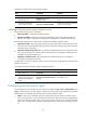
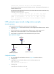
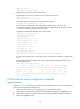
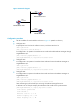
Figure 79 Network diagram
Configuration procedure
• Set the IP address for each interface as shown in Figure 79. (Details not shown.)
• Configure LB C:
# Specify the local clock as the reference source, with the stratum level 2.
<LBC> system-view
[LBC] ntp-service refclock-master 2
# Configure LB C to operate in broadcast server mode and send broadcast messages through
GigabitEthernet 0/1.
[LBC] interface gigabitethernet 0/1
[LBC-GigabitEthernet0/1] ntp-service broadcast-server
• Configure LB A:
# Configure LB A to operate in broadcast client mode and receive broadcast messages on
GigabitEthernet 0/1.
<LBA> system-view
[LBA] interface gigabitethernet 0/1
[LBA-GigabitEthernet0/1] ntp-service broadcast-client
• Configure LB B:
# Configure LB B to operate in broadcast client mode and receive broadcast messages on
GigabitEthernet 0/1.
<LBB> system-view
[LBB] interface gigabitethernet 0/1
[LBB-GigabitEthernet0/1] ntp-service broadcast-client
LB A and LB B get synchronized upon receiving a broadcast message from LB C.
# Take LB A as an example. Display the NTP status of LB A after clock synchronization.
[LBA-GigabitEthernet0/1] display ntp-service status
Clock status: synchronized
Clock stratum: 3
Reference clock ID: 3.0.1.31
Nominal frequency: 64.0000 Hz
Actual frequency: 64.0000 Hz
GE0/1
3.0.1.31/24
GE0/1
3.0.1.32/24
LB A
NTP broadcast client
LB C
NTP broadcast server
LB B
NTP broadcast client
GE0/1
3.0.1.30/24