
F3215-HP Load Balancing Module System Management Configuration Guide-6PW101

126
[Device] interface gigabitethernet 0/2
[Device-GigabitEthernet0/2] pim dm
• Configure LB A:
<LBA> system-view
[LBA] interface gigabitethernet 0/1
# Configure LB A to operate in multicast client mode and receive multicast messages on
GigabitEthernet 0/1.
[LBA-GigabitEthernet0/1] ntp-service multicast-client
# Display the NTP status of LB A after clock synchronization.
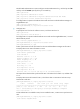
[LBA-GigabitEthernet0/1] display ntp-service status
Clock status: synchronized
Clock stratum: 3
Reference clock ID: 3.0.1.31
Nominal frequency: 64.0000 Hz
Actual frequency: 64.0000 Hz
Clock precision: 2^7
Clock offset: 0.0000 ms
Root delay: 40.00 ms
Root dispersion: 10.83 ms
Peer dispersion: 34.30 ms
Reference time: 16:02:49.713 UTC Sep 19 2012 (C6D95F6F.B6872B02)
The output shows that LB A has synchronized to LB B. The stratum level of LB A is 3, and that of LB
B is 2.
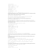
# Display NTP session information for LB A, which shows that an association has been set up
between LB A and LB B.
[LBA-Ethernet0/1] display ntp-service sessions
source reference stra reach poll now offset delay disper
**************************************************************************
[1234] 3.0.1.31 127.127.1.0 2 255 64 26 -16.0 40.0 16.6
note: 1 source(master),2 source(peer),3 selected,4 candidate,5 configured
Total associations : 1
Configuration example for NTP client/server mode with
authentication
In this example, Device B is the LB module.
Network requirements
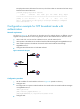
As shown in Figure 81, perform the following configurations to synchronize the time between Device B
and Device A and ensure network security.
• The local clock of Device A is to be configured as a reference source, with the stratum level 2.
• Device B operates in client mode and Device A is to be used as the NTP server of Device B, with
Device B as the client.
• NTP authentication is to be enabled on both Device A and Device B.