
F3215-HP Load Balancing Module System Management Configuration Guide-6PW101


84
Web login control configuration example
Network requirements
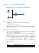
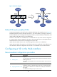
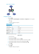
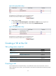
Configure the LB module in Figure 47 to provide Web access service only to Host B.
Figure 47 Network diagram
Configuration procedure
# Create ACL 2030, and configure rule 1 to permit packets sourced from Host B.
<LB> system-view
[LB] acl number 2030 match-order config
[LB-acl-basic-2030] rule 1 permit source 10.110.100.52 0
# Associate the ACL with the HTTP service so only the Web users on Host B can access the LB module.
[LB] ip http acl 2030
Displaying online users
Online users refer to the users who have passed authentication and got online. You can view information
about online users on the Web page of the device.
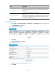
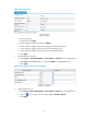
To display online users, select System > User from the navigation tree and click the Online User tab.
Figure 48 Online users
Table 19 Online user fields
Field Descri
p
tion
User ID Identity of the online user in the system.
User Name Username used for authentication.
IP Address IP address of the user's host.
Host B
10.110.100.52
LB
IP network
Host A
10.110.100.46