
F3215-HP Load Balancing Module System Management Configuration Guide-6PW101


87
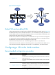
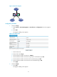
Figure 50 Network diagram
Default VD and non-default VDs
A device supporting VDs is a VD itself, and it is called the "default VD" (for example, Device in Figure 50).
The default VD always uses the name Root and the ID 1. You cannot delete it or change its name or ID.
From the default VD, you can manage the whole physical device, create and delete non-default VDs, and
assign interface and VLAN resources to non-default VDs.
No VDs can be created on a non-default VD. A non-default VD can only use the resources assigned to
it. It cannot use the resources assigned to other VDs or the remaining resources on the physical device.
The default VD can use the resources not assigned to any other VDs.
Unless otherwise stated, the term "VD" in the following sections refers to a non-default VD.
Unless otherwise stated, all operations in the following sections are performed on the default VD. For
more information about the configurations and services on a non-default VD, see related manuals.
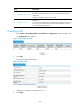
Configuring a VD in the Web interface
Recommended configuration procedure
Ste
p
Descri
p
tion
1. Creating a VD
Required.
You can create a VD and assign session resources and resources for load
balancing to the VD.
The root VD exists by default. You do not need to create it, and it cannot be
removed.
2. Assigning interfaces to VDs
Required.
By default, all Layer 3 interfaces belong to the root VD, and the other VDs
have no Layer 3 interface to use. All VDs can use the Layer 2 interfaces in
the system.
An interface can belong to only one VD at a time.