HP Firewalls and UTM Devices Attack Protection Configuration Guide Part number: 5998-4167 Software version: F1000-A-EI: Feature 3722 F1000-S-EI: Feature 3722 F5000: Feature 3211 F1000-E: Feature 3174 Firewall module: Feature 3174 Enhanced firewall module: ESS 3807 U200-A: ESS 5132 U200-S: ESS 5132 Document version: 6PW100-20121228
Legal and notice information © Copyright 2012 Hewlett-Packard Development Company, L.P. No part of this documentation may be reproduced or transmitted in any form or by any means without prior written consent of Hewlett-Packard Development Company, L.P. The information contained herein is subject to change without notice.
Contents Configuring attack detection and protection ············································································································· 1 Overview············································································································································································ 1 Types of network attacks the device can defend against ···················································································· 1 Connection limit ·····
Configuring user validity check ··························································································································· 58 Configuring ARP packet validity check ··············································································································· 59 Configuring ARP restricted forwarding ··············································································································· 59 Displaying and maintaining ARP detection ······
URPF check modes ·············································································································································· 118 URPF features ······················································································································································· 118 URPF work flow···················································································································································· 119 Network app
Configuring attack detection and protection 1B Overview 10B Attack detection and protection is an important network security feature. It determines whether received packets are attack packets according to the packet contents and behaviors and, if detecting an attack, take measures to deal with the attack, such as recording alarm logs, dropping packets, and blacklisting the source IP address.
Single-packet attack Description Route Record An attacker exploits the route record option in the IP header to probe the topology of a network. Smurf An attacker sends an ICMP echo request to the broadcast address or the network address of the target network. As a result, all hosts on the target network reply to the request, causing the network congested and hosts on the target network unable to provide services.
• ICMP flood attack An attacker sends a large number of ICMP requests to the target in a short time by, for example, using the ping program, causing the target too busy to process normal services. • UDP flood attack An attacker sends a large number of UDP packets to the target in a short time, making the target too busy to process normal services.
cracking login passwords through repeated login attempts. The maximum number of login failures is six, the blacklist entry aging time is 10 minutes, and they are not configurable. The device also allows you to add and delete blacklist entries manually. Blacklist entries added manually can be permanent blacklist entries or non-permanent blacklist entries. A permanent entry always exists in the blacklist unless you delete it manually. You can configure the aging time of a non-permanent entry.
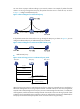
You can choose a proper mode according to your network scenario. For example, if packets from TCP clients to a server go through the TCP proxy but packets from the server to clients do not, as shown in Figure 1, configure unidirectional proxy. 265H Figure 1 Network diagram for unidirectional proxy If all packets between TCP clients and a server go through the TCP proxy, as shown in Figure 2, you can configure unidirectional proxy or bidirectional proxy as desired.
Unidirectional proxy mode can satisfy the requirements of most environments. Generally, servers do not initiate attacks to clients, and packets from servers to clients do not need to be inspected by the TCP proxy. In this case, you can configure a TCP proxy to inspect only packets that clients send to servers. To filter packets destined to clients, you can deploy a firewall as required. The unidirectional proxy mode requires that the clients use the standard TCP protocol suite.
Configuring attack detection and protection in the Web interface 1B Configuring packet inspection 54B 1. From the navigation tree, select Intrusion Detection > Packet Inspection. Figure 5 Packet inspection configuration page 2. Configure packet inspection, as described in Table 2. 3. Click Apply. 268H Table 2 Configuration items Item Description Zone Select a zone to detect attacks from the zone.
Item Description Enable IP Packet Carrying Source Route Attack Detection Enable or disable detection of source route attacks. Enable Route Record Option Attack Detection Enable or disable detection of route record attacks. Enable Large ICMP Packet Attack Detection Enable detection of large ICMP attacks and set the packet length limit, or disable detection of such attacks.
Figure 7 Enabling Land and Smurf attack detection for the untrusted zone Verifying the configuration 128B Check that the firewall can detect Land and Smurf attacks from the untrusted zone, output alarm logs accordingly, and drop the attack packets. You can select Intrusion Detection > Statistics from the navigation tree to view the counts of Land and Smurf attacks and the counts of dropped attack packets.
Figure 8 ICMP flood detection configuration page 2. Select a security zone. 3. In the Attack Prevention Policy area, select the Discard packets when the specified attack is detected box. Click Apply. If you do not select the box, the device only collects ICMP flood attack statistics. 4. In the ICMP Flood Configuration area, click Add. Figure 9 Adding an ICMP flood detection rule 5. Configure an ICMP flood detection rule, as described in Table 3. 6. Click Apply.
Table 3 Configuration items Item Description IP Address Specify the IP address of the protected host. Set the protection action threshold for ICMP flood attacks that target the protected host. Action Threshold Protected Host Configuration If the sending rate of ICMP packets destined for the specified IP address constantly reaches or exceeds this threshold, the device enters the attack protection state and takes attack protection actions as configured.
Figure 10 UDP flood detection configuration page 2. Select a security zone. 3. In the Attack Prevention Policy area, select the Discard packets when the specified attack is detected box. Click Apply. If you do not select the box, the device only collects UDP flood attack statistics. 4. In the UDP Flood Configuration area, click Add. Figure 11 Adding a UDP flood detection rule 5. Configure a UDP flood detection rule, as described in Table 4. 6. Click Apply.
Table 4 Configuration items Item Description IP Address Specify the IP address of the protected host. Set the protection action threshold for UDP flood attacks that target the protected host. Action Threshold Protected Host Configuration If the sending rate of UDP packets destined for the specified IP address constantly reaches or exceeds this threshold, the device enters the attack protection state and takes attack protection actions as configured.
Figure 12 DNS flood detection configuration page 2. Select a security zone. 3. In the DNS Flood Attack Prevention Policy area, select Enable DNS Flood Attack Detection, and then click Apply. The device will collect DNS flood attack statistics of the specified security zone, and output logs upon detecting DNS flood attacks. 4. In the DNS Flood Configuration area, click Add. Figure 13 Adding a DNS flood detection rule 5. Configure a DNS flood detection rule, as described in Table 5. 6. Click Apply.
Item Description Global Configuration of Security Zone Set the protection action threshold for DNS flood attacks that target a host in the protected security zone. Action Threshold If the sending rate of DNS query requests destined for a host in the security zone constantly reaches or exceeds this threshold, the device enters all extra requests and logs the event. NOTE: Host-specific settings take precedence over the global settings for security zones.
Figure 15 Adding a SYN flood detection rule 5. Configure a SYN flood detection rule, as described in Table 6. 6. Click Apply. 275H Table 6 Configuration items Item Description IP Address Specify the IP address of the protected host. Set the protection action threshold for SYN flood attacks that target the protected host.
Item Description Set the protection action threshold for SYN flood attacks that target a host in the protected security zone. Action Threshold Global Configuration of Security Zone If the sending rate of SYN packets destined for a host in the security zone constantly reaches or exceeds this threshold, the device enters the attack protection state and takes attack protection actions as configured.
Item Description Enable connection limit per dest IP Select the option to set the maximum number of connections that can be present for a destination IP address. Threshold Configuring scanning detection 134B Scanning detection is intended to detect scanning behaviors and is usually configured for an external zone. Scanning detection can be configured to add blacklist entries automatically. To configure scanning detection: 1.
Configure the firewall to perform the following operations: • Protect the internal network against scanning attacks from the external network. • Limit the number of connections initiated by each internal host. • Limit the number of connections to the internal server. • Protect the internal server against SYN flood attacks from the external network.
Figure 19 Enabling the blacklist feature 3. Configure scanning detection for the untrusted zone: a. From the navigation tree, select Intrusion Detection > Traffic abnormality > Scanning Detection. The scanning detection configuration page appears, as shown in Figure 20. 280H b. Select the security zone Untrust. c. Select Enable Scanning Detection. d. Set the scanning threshold to 4500 connections per second. e. Select Add the source IP to the blacklist. f. Click Apply.
Figure 21 Configuring connection limit for the trusted zone 5. Configure connection limits for the DMZ on the connection limit configuration page: a. Select the security zone DMZ. b. Select Discard packets when the specified attack is detected. c. Select Enable connection limit per dest IP and set the threshold to 10000. d. Click Apply. Figure 22 Configuring connection limit for the DMZ 6. Configure SYN flood detection for the DMZ: a.
e. In the SYN Flood Configuration area, click Add. f. The SYN flood attack detection page appears, as shown in Figure 24. 283H g. Select Protected Host Configuration. Enter the IP address 10.1.1.2. Set the action threshold to 5000 packets per second and the silent threshold to 1000 packets per second. h. Click Apply.
Task Remarks Required. Enabling TCP Proxy for a security 2. By default, the TCP proxy feature is disabled globally. 285H TIP: The TCP proxy feature takes effect only for the incoming traffic of the security zone. At least one method is required. You can add protected IP address entries by either of the methods: Adding a protected IP address entry 3. 286H • Static—Add entries manually. By default, no such entries are configured in the system.
The icon in the Status column changes to , which indicates that the TCP proxy feature is enabled. You can click Disable to disable the feature. The icon indicates that the TCP proxy feature is disabled. Adding a protected IP address entry 142B 1. Select Intrusion Detection > TCP Proxy > Protected IP Configuration to enter the page shown in Figure 26. 291H The page lists information about protected IP address entries and the relative statistics. Figure 26 Protected IP address entries 2.
Item Description Lifetime(min) Lifetime for the IP address entry under protection. This item is displayed as – for static IP address entries. When the time reaches 0, the protected IP address entry is deleted. Number of Rejected Amount of requests for TCP connection requests matching the protected IP address entry but were proved to be illegitimate.
Figure 29 Select the bidirectional mode and enable TCP proxy for zone Untrust b. Select Bidirection for the global setting, and click Apply. c. 3. In the Zone Configuration area, click Enable for the Untrust zone. Add an IP address entry manually for protection: a. From the navigation tree, select Intrusion Detection > TCP Proxy > Protected IP Configuration. b. Click Add. c. Enter 20.0.0.10 in the Protected IP Address field. d. Click Apply. Figure 30 Add an IP address entry for protection e.
Figure 31 Configure the action to be taken upon detecting a SYN flood v In the SYN Flood Configuration area, click Add. vi Select Global Configuration of Security Zone. vii Click Apply. Figure 32 Configure global settings Configuring blacklist 60B Recommended configuration procedure 146B Step Remarks Enabling the blacklist function Required. Adding a blacklist entry manually Optional. 1. 2. 295H 294H By default, the blacklist function is disabled. By default, no blacklist entries exist.
Step Remarks 4. Optional. Configuring the scanning detection feature to add blacklist entries automatically By default, the scanning detection feature is disabled. Viewing the blacklist Optional. 3. 297H For more information about scanning detection configuration, see "Configuring traffic abnormality detection." 296H Enabling the blacklist function 147B 1. From the navigation tree, select Intrusion Detection > Blacklist. The blacklist management page appears, as shown in Figure 33. 298H 2.
Table 10 Configuration items Item Description IP Address Specify the IP address to be blacklisted. Hold Time Configure the entry to be a non-permanent one and specify a lifetime for it. Permanence Configure the entry to be a permanent one. Viewing the blacklist 149B Select Intrusion Detection > Blacklist from the navigation tree to enter the blacklist management page, where you can view the blacklist information. Table 11 describes the blacklist fields.
Figure 35 Network diagram Host A Host B GE0/2 192.168.1.1/16 Trust GE0/1 202.1.0.1/16 Internet Untrust Firewall Host D 5.5.5.5/24 Host C 192.168.1.5/16 Configuring the firewall 15B 1. Assign IP addresses and security zones to the interfaces. (Details not shown.) 2. Enable the blacklist feature: a. From the navigation tree, select Intrusion Detection > Blacklist. b. The blacklist management page appears, as shown in Figure 36. 30H c.
Figure 37 Adding a blacklist entry for Host D d. In the Blacklist Configuration area, click Add again. e. On the page that appears (see Figure 38), enter the IP address 192.168.1.5, select Hold Time 305H and set the lifetime of the entry to 50 minutes. f. Click Apply. Figure 38 Adding a blacklist entry for Host C 4. Configure scanning detection for the untrusted zone, as shown in Figure 39: 306H a. From the navigation tree, select Intrusion Detection > Traffic Abnormality > Scanning Detection. b.
The firewall discards all packets from Host D before you remove the blacklist entry for the host. If the firewall receives packets from Host C, the firewall discards all packets from Host C within 50 minutes. After 50 minutes, the firewall forwards packets from Host C normally. The firewall outputs an alarm log and adds the IP address to the blacklist when detecting a scanning attack from the untrusted zone.
Attack type Description ICMP Unreachable Upon receiving an ICMP unreachable response, some systems conclude that the destination is unreachable and drop all subsequent packets destined for the destination. By sending ICMP unreachable packets, an ICMP unreachable attacker can cut off the connection between the target host and the network.
Attack type Description DNS Flood A DNS flood attack overwhelms the victim with an enormous number of DNS query requests in a short period. This disables the victim from providing normal services. Number of connections per source IP exceeds the threshold When an internal user initiates a large number of connections to a host on the external network in a short period of time, system resources on the device are used up soon. This makes the device unable to service other users.
Creating an attack protection policy 64B Before configuring attack protection functions for a security zone, you need to create an attack protection policy and enter its view. In attack protection policy view, you can define one or more signatures used for attack detection and specify the corresponding protection measures. When creating an attack protection policy, you can also specify a security zone so that the security zone uses the policy exclusively.
Step Command Remarks 2. Enter VD system view. switchto vd vd-name Required for a non-default VD. 3. Enter attack protection policy view. attack-defense policy policy-number N/A 4. Enable signature detection for single-packet attacks. signature-detect { fraggle | icmp-redirect | icmp-unreachable | land | large-icmp | route-record | smurf | source-route | tcp-flag | tracert | winnuke } enable By default, signature detection is disabled for all kinds of single-packet attacks. 5.
Step Command Remarks • Enable the blacklist 6. 7. 8. Configure the blacklist function for scanning attack protection. Return to system view. Enable the blacklist function. function for scanning attack protection: defense scan add-to-blacklist • Set the aging time for entries blacklisted by the scanning attack protection function: defense scan blacklist-timeout minutes Optional. By default: • The blacklist function for scanning attack protection is disabled.
Step Command Remarks Optional. 5. Configure the global action and silence thresholds for SYN flood attack protection. defense syn-flood rate-threshold high rate-number [ low rate-number ] By default, the action threshold is 1000 packets per second and the silence threshold is 750 packets per second. 6. Configure the action and silence thresholds for SYN flood attack protection of a specific IP address. defense syn-flood ip ip-address rate-threshold high rate-number [ low rate-number ] Optional.
Step Command Remarks Optional. 5. Configure the global action and silence thresholds for UDP flood attack protection. defense udp-flood rate-threshold high rate-number [ low rate-number ] By default, the action threshold is 1000 packets per second and the silence threshold is 750 packets per second. 6. Configure the action and silence thresholds for UDP flood attack protection for a specific IP address. defense udp-flood ip ip-address rate-threshold high rate-number [ low rate-number ] Optional.
Step 4. Command Remarks By default, no attack protection policy is applied to any security zone. attack-defense apply policy policy-number Apply an attack protection policy to the security zone. The attack protection policy to be applied to a security zone must already exist. Configuring TCP proxy 68B Usually, TCP proxy is used on a device's security zones connected to external networks to protect internal servers from SYN flood attacks.
Step Command Remarks 2. Enter VD system view. switchto vd vd-name Required for a non-default VD. 3. Enable the blacklist function. blacklist enable Disabled by default. Add a blacklist entry. blacklist ip source-ip-address [ timeout minutes ] Optional. 4. The scanning attack protection function can add blacklist entries automatically. You can add blacklist entries manually, or configure the device to automatically add the IP addresses of detected scanning attackers to the blacklist.
Task Command Remarks Display the traffic statistics of a security zone. display flow-statistics statistics [ vd vd-name ] zone zone-name { inbound | outbound } [ | { begin | exclude | include } regular-expression ] Available in any view. Display the security zone traffic statistics based on IP addresses.
Figure 41 Network diagram Configuration procedure 158B # Specify IP address for interfaces and add them into security zones. (Details not shown.) # Enable blacklist function. system-view [Firewall] blacklist enable # Create attack protection policy 1. [Firewall] attack-defense policy 1 # Enable Smurf attack protection. [Firewall-attack-defense-policy-1] signature-detect smurf enable # Enable scanning attack protection.
# Configure the policy to drop the subsequent packets after a SYN flood attack is detected. [Firewall-attack-defense-policy-2] defense syn-flood action drop-packet [Firewall-attack-defense-policy-2] quit # Apply attack protection policy 2 to security zone DMZ. [Firewall] zone name dmz id 3 [Firewall-zone-dmz] attack-defense apply policy 2 [Firewall-zone-dmz] quit Verifying the configuration 159B Use the display attack-defense policy command to display the contents of attack protection policy 1 and 2.
[Firewall] blacklist ip 192.168.1.4 timeout 50 Verifying the configuration 162B Use the display blacklist all command to display the added blacklist entries. [Firewall] display blacklist all Blacklist information ------------------------------------------------------------------------Blacklist : enabled Blacklist items : 2 -----------------------------------------------------------------------------IP Type Aging started Aging finished Dropped packets YYYY/MM/DD hh:mm:ss YYYY/MM/DD hh:mm:ss 5.5.5.
[Firewall-attack-defense-policy-1] defense udp-flood enable # Set the global action threshold that triggers UDP flood attack protection to 100 packets per second. [Firewall-attack-defense-policy-1] defense udp-flood rate-threshold high 100 # Configure the policy to drop the subsequent packets after a UDP flood attack is detected. [Firewall-attack-defense-policy-1] defense udp-flood action drop-packet [Firewall-attack-defense-policy-1] quit # Apply attack protection policy 1 to security zone trust.
Total number of existing sessions : 13676 Session establishment rate : 2735/s TCP sessions : 0 Half-open TCP sessions : 0 Half-close TCP sessions : 0 TCP session establishment rate : 0/s UDP sessions : 13676 UDP session establishment rate : 2735/s ICMP sessions : 0 ICMP session establishment rate : 0/s RAWIP sessions : 0 RAWIP session establishment rate : 0/s The output shows that in security zone trust, a large number of UDP packets are destined for 10.1.1.
system-view [Firewall] attack-defense policy 1 # Enable SYN flood attack protection. [Firewall-attack-defense-policy-1] defense syn-flood enable # Set the global action threshold for SYN flood attack protection to 100 packets per second. [Firewall-attack-defense-policy-1] defense syn-flood rate-threshold high 100 # Configure the device to use the TCP proxy for subsequent packets after a SYN flood attack is detected.
Configuring ARP attack protection 2B ARP attacks and viruses threaten LAN security. This chapter describes multiple features used to detect and prevent such attacks. Overview 13B Although ARP is easy to implement, it provides no security mechanism and is vulnerable to network attacks. An attacker can exploit ARP vulnerabilities to attack network devices in the following ways: • Acts as a trusted user or gateway to send ARP packets so the receiving devices obtain incorrect ARP entries.
Task Remarks Configuring ARP automatic scanning and fixed ARP Optional. 31H Configure this function on gateways (recommended). Configuring unresolvable IP attack protection 15B Unresolvable IP attack protection can be configured only at the CLI. If a device receives from a host a large number of IP packets that cannot be resolved by ARP (called unresolvable IP packets), the following situations can occur: • The device sends a large number of ARP requests, overloading the target subnets.
Displaying and maintaining ARP source suppression 7B Task Command Remarks Display the ARP source suppression configuration information. display arp source-suppression [ | { begin | exclude | include } regular-expression ] Available in any view. Unresolvable IP attack protection configuration example 16B Network requirements 169B As shown in Figure 45, a LAN contains two areas: an R&D area in VLAN 10 and an office area in VLAN 20.
If the attack packets have different source addresses, enable the ARP black hole routing function on the firewall. Configuration procedure 17B # Enable ARP source suppression and set the threshold to 100. system-view [Firewall] arp source-suppression enable [Firewall] arp source-suppression limit 100 # Enable ARP black hole routing.
Step Command Remarks Enable source MAC address based ARP attack detection and specify the handling method. arp anti-attack source-mac { filter | monitor } Disabled by default. 3. Configure the threshold. arp anti-attack source-mac threshold threshold-value Optional. 4. Configure the lifetime for ARP attack entries. arp anti-attack source-mac aging-time time Optional. Configure excluded MAC addresses. arp anti-attack source-mac exclude-mac mac-address&<1-n> 2. 5. 50 by default.
Figure 46 Network diagram IP network ARP attack protection Gateway Firewall Server 0012-3f86-e94c Host A Host B Host C Host D Configuration considerations 173B An attacker may forge a large number of ARP packets by using the MAC address of a valid host as the source MAC address. To prevent such attacks, configure the gateway as follows: 1. Enable source MAC address based ARP attack detection and specify the handling method. 2. Set the threshold. 3. Set the lifetime for ARP attack entries. 4.
The following matrix shows the feature and hardware compatibility: Hardware ARP packet source MAC consistency check compatible F1000-A-EI/F1000-S-EI Yes F1000-E No F5000 No Firewall module No U200-A Yes U200-S Yes This feature enables a gateway to filter out ARP packets whose source MAC address in the Ethernet header is different from the sender MAC address in the message body, so that the gateway can learn correct ARP entries.
Step 2. Enable the ARP active acknowledgement function. Command Remarks arp anti-attack active-ack enable Disabled by default. Configuring periodic sending of gratuitous ARP packets 20B Periodic sending of gratuitous ARP packet can be configured only in the Web interface. Enabling a device to periodically send gratuitous ARP packets helps downstream devices update their corresponding ARP entries or MAC entries in time.
VLAN termination configured can use the gratuitous ARP packets to update their corresponding MAC entries in time. For more information about VRRP, see High Availability Web-based Configuration Guide. Configuration restrictions and guidelines 80B • You can enable periodic sending of gratuitous ARP packets on a maximum of 1024 interfaces. • Periodic sending of gratuitous ARP packets takes effect only when the link of the enabled interface goes up and an IP address has been assigned to the interface.
Configuring ARP detection 21B The following matrix shows the feature and hardware compatibility: Hardware ARP detection compatible F1000-A-EI/F1000-S-EI Yes F1000-E No F5000 No Firewall module No U200-A Yes U200-S Yes ARP detection enables access devices to block ARP packets from unauthorized clients to prevent user spoofing and gateway spoofing attacks. ARP detection provides the user validity check, ARP packet validity check, and ARP restricted forwarding functions.
Step Command Configure the interface as a trusted interface excluded from ARP detection. 7. Remarks arp detection trust Optional. By default, an interface is untrusted. Configuring ARP packet validity check 83B Enable validity check for ARP packets received on untrusted ports and specify the following objects to be checked: • src-mac—Checks whether the sender MAC address in the message body is identical to the source MAC address in the Ethernet header. If they are identical, the packet is forwarded.
Step Command Remarks 1. Enter system view. system-view N/A 2. Enter VLAN view. vlan vlan-id N/A 3. Enable ARP restricted forwarding. arp restricted-forwarding enable By default, ARP restricted forwarding is disabled. Displaying and maintaining ARP detection 85B Task Command Remarks Display the VLANs enabled with ARP detection. display arp detection [ | { begin | exclude | include } regular-expression ] Available in any view. Display the ARP detection statistics.
• The static ARP entries changed from dynamic ARP entries have the same attributes as the manually configured static ARP entries. • The number of static ARP entries changed from dynamic ARP entries is restricted by the number of static ARP entries that the device supports. As a result, the device may fail to change all dynamic ARP entries into static ARP entries. • The fixing process may take some time, during which some dynamic entries may be added or be aged out.
Item Description Specify the start and end IP addresses of the IP address range for ARP automatic scanning. Start IP Address To reduce the scanning time, you can specify the IP address range for scanning if you know the IP address range assigned to the neighbors in a LAN. The specified start and end IP addresses must be in the same network segment as the primary IP address or manually configured secondary IP address of the interface.
5. Select the box before static ARP entries, and click Del Fixed to delete the selected static ARP entry. If you select a dynamic one and click Del Fixed, the entry is not deleted. Configuring the ARP automatic scanning and fixed ARP at the CLI 86B Configuration guidelines 179B When you configure ARP automatic scanning and fixed ARP, follow these guidelines: • IP addresses existing in ARP entries are not scanned. • ARP automatic scanning may take some time. To stop an ongoing scan, press Ctrl + C.
Configuring TCP attack protection 3B TCP attack protection can be configured only at the CLI. Overview 24B Attackers can attack the device during the process of TCP connection establishment. To prevent such attacks, the device provides the following features: • SYN Cookie • Protection against Naptha attacks This chapter describes the attacks that these features can prevent, working mechanisms of these features, and configuration procedures.
Enabling protection against Naptha attacks 26B Naptha attacks are similar to the SYN Flood attacks. Attackers can perform Naptha attacks by using the six TCP connection states (CLOSING, ESTABLISHED, FIN_WAIT_1, FIN_WAIT_2, LAST_ACK, and SYN_RECEIVED), and SYN Flood attacks by using only SYN_RECEIVED state.
Configuring ND attack defense 4B ND attack defense can be configured only at the CLI. Feature and hardware compatibility 28B Hardware ND attack defense compatible F1000-A-EI/F1000-S-EI Yes F1000-E Yes F5000 Yes Firewall module Yes U200-A Yes U200-S No Overview 29B The IPv6 Neighbor Discovery (ND) protocol provides rich functions, such as address resolution, neighbor reachability detection, duplicate address detection, router/prefix discovery and address autoconfiguration, and redirection.
Figure 50 ND attack diagram All forged ND packets have two common features: • The Ethernet frame header and the source link layer address option of the ND packet contain different source MAC addresses. • The mapping between the source IPv6 address and the source MAC address in the Ethernet frame header is invalid. To identify forged ND packets, HP developed the source MAC consistency check feature.
Configuring firewall 5B The term "router" in this document refers to both routers and routing-capable firewalls and UTM devices. Overview 31B A firewall blocks unauthorized Internet access to a protected network while allowing internal network users to access the Internet through WWW, or to send and receive e-mails. A firewall can also be used to control access to the Internet, for example, to permit only specific hosts within the organization to access the Internet.
ASPF 8B Application Specific Packet Filter (ASPF) was proposed to address the issues that a static firewall cannot solve. An ASPF implements application layer and transport specific, namely status-based, packet filtering. An ASPF can detect application layer protocols including FTP, GTP, HTTP, SMTP, Real RTSP, SCCP, SIP, H.323 (Q.931, H.245, and RTP/RTCP), and transport layer protocols TCP and UDP.
{ { • Single-channel protocol—A single-channel protocol establishes only one channel to exchange both control messages and data for a user. SMTP and HTTP are examples of single-channel protocols. Multi-channel protocol—A multi-channel protocol establishes more than one channel for a user and transfers control messages and user data through different channels. FTP and RTSP are examples of multi-channel protocols.
multi-channel application layer protocols like FTP and H.323, the deployment of TCP detection without application layer detection will lead to failure of establishing a data connection. Configuring an IPv6 packet-filter firewall 32B IPv6 packet-filter firewall can be configured only at the CLI.
Configuring packet filtering on an interface 92B When an ACL is applied to an interface, the time range-based filtering will also work at the same time. In addition, you can specify separate access rules for inbound and outbound packets. The effective range for basic ACL numbers is 2000 to 2999. A basic ACL defines rules based on the Layer 3 source IP addresses only to analyze and process data packets. The effective range for advanced ACL numbers is 3000 to 3999.
Configuring an ASPF 3B ASPF can be configured at the CLI and in the Web interface. This section describes only the CLI configuration for ASPF. For ASPF configuration in the Web interface, see Access Control Configuration Guide. ASPF configuration task list 93B Task Remarks Configuring port mapping Optional. Enabling ASPF for an interzone instance Required. 340H 341H Configuring port mapping 94B Two mapping mechanisms exist: general port mapping and basic ACL–based host port mapping.
Step 4. Enable ASPF for the interzone instance. Command Remarks firewall aspf enable [ icmp-error drop | tcp syn-check ] Disabled by default. For more information about security zones, see Access Control Configuration Guide. Displaying ASPF 96B Task Command Remarks Display the port mapping information. display port-mapping [ application-name | port port-number ] [ | { begin | exclude | include } regular-expression ] Available in any view.
Configuring content filtering 6B Overview 34B Content filtering enables the device to filter contents carried in HTTP packets, SMTP packets, POP3 packets, FTP packets, and Telnet packets, to prevent internal users from accessing illegal websites or sending junk emails and prevent packets carrying illegal contents from entering the internal network. Upon receiving HTTP, SMTP, POP3, FTP, or Telnet packets, the device first matches the packets against interzone policies.
SMTP packet content filtering 9B The SMTP packet content filtering, hereafter referred to as SMTP filtering, provides the following functions: • Sender filtering—Filters sender addresses in SMTP requests, to prevent specified senders from sending emails. • Receiver filtering—Filters receiver addresses (including recipients and carbon copy or named CC recipients) in SMTP requests, to prevent internal users from sending emails to the specified receiver addresses.
• Download filename filtering—Filters filenames carried in FTP download requests, to prevent clients from downloading files with the specified names from the server. Telnet packet content filtering 102B Telnet packet content filtering, hereafter referred to as Telnet filtering, filters command words in Telnet requests. Telnet filtering prevents Telnet users from executing specific commands, such as format and reboot, which greatly affect the normal operation of the device.
{ { { The asterisk (*) matches any string of up to 4 characters, including spaces. It can be used only once in a keyword and must not be at the beginning or end. A keyword with caret (^) at the beginning or dollar sign ($) at the end indicates an exact match. For example, keyword ^webfilter$ matches URLs containing standalone word webfilter, like www.abc.com/webfilter any; it does not match URLs like www.abc.com/webfilterany.
Step Description Keyword filtering entries include: • HTTP keyword filtering entries—For header filtering and body filtering in HTTP filtering policies. • SMTP keyword filtering entries—For subject filtering, body filtering, and attachment content filtering in SMTP filtering policies. Configuring a keyword filtering entry 346H • POP3 keyword filtering entries—For subject filtering, body filtering, and attachment content filtering in POP3 filtering policies.
Figure 53 Keyword filtering entry list 2. Click Add to enter the page for adding a keyword filtering entry, as shown in Figure 54. 35H Figure 54 Adding a keyword filtering entry 3. Configure the keyword filtering entry, as described in Table 14. 4. Click Apply. 354H Table 14 Configuration items Item Description Name Specify the name of the keyword filtering entry. Specify the keywords for the keyword filtering entry. Keyword You can specify up to 16 keywords separated by commas.
Figure 56 Adding a URL hostname filtering entry 4. Configure the URL hostname filtering entry as described in Table 15. 5. Click Apply. 357H Table 15 Configuration items Item Description Name Specify the name of the URL hostname filtering entry. Specify URL hostname keywords for the URL hostname filtering entry. URL Hostname You can specify up to 16 keywords separated by commas. See "Configuration guidelines" for the rules of using wildcards. 358H Configuring filename filtering entries 19B 1.
5. Click Apply. Table 16 Configuration items Item Description Name Specify the name of the filename filtering entry. Specify filename keywords for the filename filtering entry. You can specify up to 16 filename keywords separated by commas. • If you specify a filename keyword in the format of filename.extension, the device will perform exact match for this keyword. You can use a wildcard (*) to stand for the filename part, the extension, or a string of up to 6 characters in the filename or extension.
Item Description Specify email address keywords for the email address filtering entry, in the format of username@domain name. Email Address You can specify up to 16 email address keywords separated by commas. You can use a wildcard (*) to stand for any number of characters excluding dot (.) and use it only in the format of *@domain name or *@*domain name. Configuring URL parameter filtering keywords 193B 1. From the navigation tree, select Identification > Content Filtering > Filtering Entry. 2.
See Figure 63 for the requirements on a keyword. See "Configuration guidelines" for the rules of using wildcards. A keyword string can contain spaces, but consecutive spaces are not allowed. 368H 6. 369H Click Apply. Figure 63 Adding a URL parameter filtering keyword Configuring java blocking keywords 194B 1. From the navigation tree, select Identification > Content Filtering > Filtering Entry. 2. Select the Java tab to enter the java blocking keyword list page, as shown in Figure 64.
Figure 66 ActiveX blocking keywords setup 3. Click Add to enter the page for adding an ActiveX blocking keyword, as shown in Figure 67. 4. Specify a suffix keyword for ActiveX blocking. 374H See Figure 67 for the requirements on a keyword. 375H 5. Click Apply.
Figure 68 HTTP filtering policy list 2. Click Add to enter the page for adding an HTTP filtering policy, as shown in Figure 69. 382H Figure 69 Adding an HTTP filtering policy 3. Configure the HTTP filtering policy as described in Table 18. 4. Click Apply. 38H Table 18 Configuration items Item Description Name Specify the name for the HTTP filtering policy. URL Filtering Select the filtering entries to be used for URL hostname filtering.
Item Description Specify whether to enable URL parameter filtering. URL Parameter Filtering If you select this item, all URL parameter filtering keywords are effective. Specify whether to enable ActiveX blocking. ActiveX Blocking If you select this item, all ActiveX blocking keywords are effective. Specify whether to enable java applet blocking. Java Applet Blocking If you select this item, all java blocking keywords are effective. Specify whether to log packet matching events.
Figure 71 Adding an SMTP filtering policy Table 19 Configuration items Item Description Name Specify the name for the SMTP filtering policy. Sender Filtering Select the filtering entries to be used for sender filtering. Receiver Filtering Select the filtering entries to be used for receiver filtering. Subject Filtering Select the filtering entries to be used for subject filtering. Body Filtering Select the filtering entries to be used for body filtering.
Item Description Specify whether to log packet matching events. IMPORTANT: Enable Logging The logging function takes effect only when it is enabled in both the content filtering policy and the interzone policy. Configuring a POP3 filtering policy 198B 1. From the navigation tree, select Identification > Content Filtering > Filtering Policy. 2. Select the POP3 Policy tab to enter the POP3 filtering policy list page, as shown in Figure 72. 387H Figure 72 POP3 filtering policy list 3.
Item Description Sender Filtering Select the filtering entries to be used for sender filtering. Receiver Filtering Select the filtering entries to be used for receiver filtering. Subject Filtering Select the filtering entries to be used for subject filtering. Body Filtering Select the filtering entries to be used for body filtering. Attachment Filtering Attachment Name Filtering Select the filtering entries to be used for attachment name filtering.
Figure 75 Adding an FTP filtering policy 4. Configure the FTP filtering policy, as described in Table 21. 5. Click Apply. 392H Table 21 Configuration items Item Description Name Specify the name for the FTP filtering policy. Command Filtering Select the filtering entries to be used for command word filtering. Upload Filename Filtering Select the filtering entries to be used for upload filename filtering.
3. Click Add to enter the page for adding a Telnet filtering policy, as shown in Figure 77. 394H Figure 77 Adding a Telnet filtering policy 4. Configure the Telnet filtering policy, as described in Table 22. 5. Click Apply. 395H Table 22 Configuration items Item Description Name Specify the name for the Telnet filtering policy. Select the filtering entries to be used for command word filtering. Command Filtering IMPORTANT: • Packets that match these filtering conditions will be dropped.
Figure 78 Policy template list 2. Click Add to enter the page for adding a content filtering policy template, as shown in Figure 79. 397H Figure 79 Adding a content filtering policy template 3. Configure the content filtering policy template, as described in Table 23. 4. Click Apply. 398H Table 23 Configuration items Item Description Name Enter the name of the content filtering policy template.
Displaying content filtering statistics 107B From the navigation tree, select Identification > Content Filtering > Statistic Information. The content filtering statistics page appears, as shown in Figure 80. You can view the statistics of each content filtering function. 39H Figure 80 Statistic information Content filtering configuration example 108B Network requirements 201B As shown in Figure 81, hosts in LAN segment 192.168.1.0/24 access the Internet through the firewall.
• Enable Telnet command word filtering to prevent users from executing commands that carry the command keyword reboot. Figure 81 Network diagram Configuring the firewall 20B 1. Configure IP addresses for the interfaces of the device and assign the interfaces to security zones. (Details not shown.) 2. Configure a keyword filtering entry named abc: a. From the navigation tree, select Identification > Content Filtering > Filtering Entry. The keyword filtering entry list page appears. b. Click Add. c.
Figure 83 Configuring keyword filtering entry reboot 4. Configure an SMTP filename filtering entry .exe: a. Select the Filename tab. b. Click Add. c. Enter the entry name exe, and the filename keyword *.exe as shown in Figure 84. 403H d. Click Apply. Figure 84 Configuring a filename filtering entry *.exe 5. Configure an FTP filename filtering entry system: a. Select the Filename tab, and then click Add b. Enter the entry name system, and the filename keyword system as shown in Figure 85. 40H c.
Figure 86 Configuring an HTTP filtering policy without java applet blocking 7. Configure an HTTP filtering policy with java applet blocking: a. On the HTTP filtering policy list page, click Add. b. Enter the policy name http_policy2. c. Click Body Filtering. d. Select body filtering entry abc in the available filtering entry list, and then click << to add it to the selected filtering entry list. e. Select the box before Java Applet Blocking. f. Click Apply.
Figure 87 Configuring an HTTP filtering policy with java applet blocking 8. Configure an SMTP filtering policy: a. Select the SMTP Policy tab. b. Click Add. c. Enter the policy name smtp_policy. d. Click Attachment Filtering. e. In the Attachment Name Filtering area, select filename filtering entry exe in the available filtering entry list, and then click << to add it to the selected filtering entry list. f. Click Apply.
Figure 88 Configuring an SMTP filtering policy 9. Configure an FTP filtering policy: a. Select the FTP Policy tab. b. Click Add. c. Enter the policy name ftp_policy. d. Click Upload Filename Filtering. e. Select filename filtering entry system in the available filtering entry list, and then click << to add it to the selected filtering entry list. f. Click Apply.
Figure 89 Configuring an FTP filtering policy 10. Configure a Telnet filtering policy: a. Select the Telnet tab. b. Click Add. c. Enter the policy name telnet_policy. d. Click Command Filtering. e. Select command filtering entry reboot in the available filtering entry list, and then click << to add it to the selected filtering entry list. f. Click Apply.
Figure 90 Configuring a Telnet filtering policy 11. Configure a content filtering policy template without java applet blocking: a. From the navigation tree, select Identification > Content Filtering > Policy Template. b. Click Add. c. Enter the template name template1. d. Select HTTP filtering policy http_policy1, SMTP filtering policy smtp_policy, FTP filtering policy ftp_policy, and Telnet filtering policy telnet_policy. e. Click Apply.
d. Select HTTP filtering policy http_policy2, SMTP filtering policy smtp_policy, FTP filtering policy ftp_policy, and Telnet filtering policy telnet_policy. e. Click Apply. Figure 92 Configuring a content filtering policy template with java applet blocking 13. Configure an interzone policy for traffic from security zone Trust to destination 5.5.5.5 in security zone Untrust, referencing the content filtering policy template without java applet blocking: a.
Figure 93 Configuring the interzone policy referencing the template without java applet blocking 14. Configure an interzone policy for traffic from security zone Trust to security zone Untrust, referencing the content filtering policy template with java applet blocking: a. Select Trust as the source zone and Untrust as the destination zone. b. Select any_address as the source IP address and destination IP address. c. Select any_service as the service name and Permit as the filter action. d.
Figure 94 Configuring the interzone policy referencing the template with java applet blocking Verifying the configuration 203B After the previous configurations, LAN users cannot receive HTTP responses that carry keyword abc, send java applet requests to Web servers except server 5.5.5.5, send emails with .exe attachments, upload files named abc through FTP, or execute Telnet command reboot.
Figure 95 Content filtering statistics Configuring content filtering at the CLI 37B Content filtering configuration task list 109B 1. Configure keyword filtering entries and add keywords, URL hostnames, file names, and email addresses to be filtered to each entry. You can also configure URL parameter filtering keywords, java blocking keywords, and ActiveX blocking keywords in system view.
Tasks at a glance (Required.) Configure filtering entries and keywords: • • • • • • • Configuring a keyword filtering entry 406H Configuring a URL hostname filtering entry 407H Configuring a filename filtering entry 408H Configuring an email address filtering entry 409H Configuring URL parameter filtering keywords 410H Configuring java blocking keywords 41H Configuring ActiveX blocking keywords 412H (Required.
To configure a URL hostname filtering entry: Step Commands Remarks 1. Enter system view. system-view N/A 2. Enter VD view. switchto vd vd-name Required for a non-default VD. 3. Create a URL hostname filtering entry and enter its view. content-filtering url-hostname-entry url-hostname-entry-name By default, no URL hostname filtering entry exists. 4. Add a URL hostname to the URL hostname filtering entry. url-hostname fix-string url-hostname Optional.
Step Command Remarks 1. Enter system view. system-view N/A 2. Enter VD view. switchto vd vd-name Required for a non-default VD. 3. Create an email address filtering entry and enter its view. content-filtering email-address-entry email-entry-name By default, no email address filtering entry exists. 4. Add an email address to the email address filtering entry. Optional. email-address mail-address By default, an email address filtering entry does not have any email address.
Configuring an HTTP filtering policy 21B You can specify multiple filtering entries for filtering HTTP packets in an HTTP filtering policy. Packets that match any filtering entry are dropped. An HTTP filtering policy can contain different types of filtering entries and each type can contain multiple filtering entries. To configure an HTTP filtering policy: Step Command Remarks 1. Enter system view. system-view N/A 2. Enter VD view.
Configuring an SMTP filtering policy 21B You can specify multiple filtering entries for filtering SMTP packets in an SMTP filtering policy. Packets that match any filtering entry are dropped. An SMTP filtering policy can contain different types of filtering entries and each type can contain multiple filtering entries. To configure an SMTP filtering policy: Step Command Remarks 1. Enter system view. system-view N/A 2. Enter VD view.
NOTE: • SMTP filtering policies created in system view belong to the default VD. • SMTP filtering policies created in VD view belong to the corresponding VD. Configuring a POP3 filtering policy 213B You can specify multiple filtering entries for filtering POP3 packets in a POP3 filtering policy. Packets that match any filtering entry are dropped. A POP3 filtering policy can contain different types of filtering entries and each type can contain multiple filtering entries.
NOTE: • POP3 filtering policies created in system view belong to the default VD. • POP3 filtering policies created in VD view belong to the corresponding VD. Configuring an FTP filtering policy 214B You can specify multiple filtering entries for filtering FTP packets in an FTP filtering policy. Packets that match any filtering entry are dropped. An FTP filtering policy can contain different types of filtering entries and each type can contain multiple filtering entries.
Step Command Remarks 1. Enter system view. system-view N/A 2. Enter VD view. switchto vd vd-name This command is required for entering the system view of a non-default VD. 3. Create a Telnet filtering policy and enter its view. content-filtering telnet-policy policy-name By default, no Telnet filtering policy exists. Specify a keyword filtering entry for command word filtering. command-filtering keyword-entry keyword-entry-name 4. Optional.
NOTE: • Content filtering policy templates created in system view belong to the default VD. • Content filtering policy templates created in VD view belong to the corresponding VD. Displaying and maintaining content filtering 10B Perform display commands in any view and reset commands in user view. Task Command Displaying URL parameter filtering information.
Configuration procedure 218B 1. Specify the IP addresses for the interfaces and assign the interfaces to appropriate zones. (Details not shown.) 2. Configure filtering entries: # Create a keyword filtering entry kwd1 and enter its view. system-view [Firewall] content-filtering keyword-entry kwd1 # Add a keyword abc to the entry kwd1. [Firewall-contflt-keyword-kwd1] keyword fix-string abc [Firewall-contflt-keyword-kwd1] quit # Create a keyword filtering entry kwd2 and enter its view.
# Create an FTP filtering policy ftp_policy1 and enter its view. [Firewall] content-filtering ftp-policy ftp_policy1 # Specify the filename filtering entry file2 for FTP upload filename filtering. [Firewall-contflt-ftp-policy-ftp_policy] upload-filename-filtering filename-entry file2 [Firewall-contflt-ftp-policy-ftp_policy] quit # Create a Telnet filtering policy telnet_policy1 and enter its view.
[Firewall-interzone-Trust-Untrust-rule-0] source-ip private [Firewall-interzone-Trust-Untrust-rule-0] destination-ip webserver [Firewall-interzone-Trust-Untrust-rule-0] service any_service [Firewall-interzone-Trust-Untrust-rule-0] rule enable [Firewall-interzone-Trust-Untrust-rule-0] quit # Configure another interzone policy rule that uses the content filtering policy template 2 with java Applet blocking enabled to filter HTTP packets from subnet 192.168.1.0/24 to external networks.
Configuring URPF 7B The term "router" in this document refers to both routers and routing-capable firewalls and UTM devices. Overview 38B Unicast Reverse Path Forwarding (URPF) protects a network against source spoofing attacks, such as denial of service (DoS) and distributed denial of service (DDoS) attacks. Attackers send packets with a forged source address to access a system that uses IP-based authentication, in the name of authorized users or even the administrator.
• ACL—To identify specific packets as valid packets, you can use an ACL to match these packets. Even if the packets do not pass URPF check, they are still forwarded normally. URPF work flow 14B URPF does not check multicast packets. Figure 98 shows how URPF works.
{ { 2. 3. { If yes, proceeds to step 3. { If not, proceeds to step 5. URPF checks whether the matching route is a default route: { If yes, URPF checks whether the allow-default-route keyword is configured—If yes, proceeds to step 4. If not, proceeds to step 5. If not, proceeds to step 4. URPF checks whether the receiving interface matches the output interface of the matching FIB entry: { { 5. Proceeds to step 2 for other packets.
Configure ACLs for special packets or users. • Configuring the URPF in the Web interface 39B Configuring URPF 16B 1. From the navigation tree, select Intrusion Detection > URPF Check to enter the URPF check configuration page, as shown in Figure 100. 42H Figure 100 URPF check configuration page 2. Configure URPF settings for the security zone, as shown in Table 24. 3. Click Apply. 423H Table 24 Configuration items Item Description Security zone where the URPF check is to be configured.
Network requirements 20B As shown in Figure 101, Device A (CE) directly connects to Device B (PE). Enable strict URPF check in Zone B of Device B to allow packets whose source addresses match ACL 2010 to pass. Enable strict URPF check in Zone A of Device A and allow use of the default route for URPF check. 42H Figure 101 Network diagram Configuring Device B 21B 1. Configure the interface IP addresses and security zones they belong to. (Details not shown.) 2.
Figure 103 Configuring ACL 2010 3. Enable strict URPF check in Zone B: a. From the navigation tree, select Intrusion Detection > URPF Check. The URPF configuration page appears, as shown in Figure 104. 427H b. Select zoneB in Security Zone. c. Select Enable URPF. d. Select ACL and type 2010 in the field. e. Select Strict in Type of Check. f. Click Apply. Figure 104 Configuring URPF in zoneB Configuring Device A 2B 1. Configure the interface IP addresses and security zones they belong to.
d. Select Allow Default Route. e. Select Strict in Type of Check. f. Click Apply. Figure 105 Configuring URPF on zoneA Configuring the URPF at the CLI 40B Configuring URPF 18B Perform this task to configure URPF for a security zone. URPF checks only incoming packets on a zone Do not configure the allow-default-route keyword for loose URPF check. Otherwise, URPF might fail to work. To enable URPF: Step 1. Enter system view. Command Remarks system-view N/A Optional. 2.
Network requirements 23B As shown in Figure 106, configure strict URPF check for zoneB on Device B to permit packets from network 10.1.1.0/24. 429H Enable strict URPF check for zoneA on Device A and allow using the default route for URPF check. Figure 106 Network diagram Configuration procedure 24B 1. Assign IP addresses for interfaces and add them into security zones. (Details not shown.) 2. Configure Device B: # Define ACL 2010 to permit traffic from network 10.1.1.0/24 to pass.
Configuring IDS collaboration 8B The firewall device can collaborate with only Venusense IDS devices. IDS collaboration can be configured only in the Web interface.
Figure 108 Enable IDS collaboration 2. Select the Enable IDS Collaboration box. 3. Click Apply. Configuration guidelines 4B When you configure IDS collaboration, follow these guidelines: • Both the firewall devices and IDS devices must support and have SNMPv2c configured. • The aging time for an IDS blocking entry is five minutes. The timer restarts if the firewall receives an SNMP trap with the same attack information before the timer expires.
Support and other resources 9B Contacting HP 45B For worldwide technical support information, see the HP support website: http://www.hp.
Conventions 47B This section describes the conventions used in this documentation set. Command conventions 25B Convention Description Boldface Bold text represents commands and keywords that you enter literally as shown. Italic Italic text represents arguments that you replace with actual values. [] Square brackets enclose syntax choices (keywords or arguments) that are optional. { x | y | ...
Network topology icons 28B Represents a generic network device, such as a router, switch, or firewall. Represents a routing-capable device, such as a router or Layer 3 switch. Represents a generic switch, such as a Layer 2 or Layer 3 switch, or a router that supports Layer 2 forwarding and other Layer 2 features. Represents a firewall product or a UTM device. Port numbering in examples 29B The port numbers in this document are for illustration only and might be unavailable on your device.
Index 0B ACDEFIORU 132H 13H 134H 135H 136H 137H 138H 139H 140H A D ARP attack protection configuration task list,49 Displaying and maintaining TCP attack protection,65 C E 431H 452H Configuration guidelines,127 Enabling IDS collaboration,126 Configuration guidelines,77 Enabling protection against Naptha attacks,65 Configuring an ASPF,73 Configuring an IPv6 packet-filter firewall,71 Enabling source MAC consistency check for ND packets,67 Configuring ARP active acknowledgement,55 Enab