HP Firewalls and UTM Devices High Availability Configuration Guide Part number: 5998-4169 Software version: F1000-A-EI: Feature 3722 F1000-S-EI: Feature 3722 F5000: Feature 3211 F1000-E: Feature 3174 Firewall module: Feature 3174 Enhanced firewall module: ESS 3807 U200-A: ESS 5132 U200-S: ESS 5132 Document version: 6PW100-20121228
Legal and notice information © Copyright 2012 Hewlett-Packard Development Company, L.P. No part of this documentation may be reproduced or transmitted in any form or by any means without prior written consent of Hewlett-Packard Development Company, L.P. The information contained herein is subject to change without notice.
Contents Legal and notice information·········································································································································i High availability overview··········································································································································· 1 Availability requirements ··············································································································································
Operating procedure ············································································································································ 51 Service backup ······················································································································································ 52 Configuration synchronization ····························································································································· 52 Stateful failover st
Collaboration group configuration example ······································································································ 98 Configuring NQA ······················································································································································ 99 Overview········································································································································································· 99 Collaboratio
Configuring an aggregation group ··················································································································· 152 Configuring an aggregate interface ················································································································· 156 Configuring load-sharing criteria for link aggregation groups ······································································ 160 Displaying and maintaining Ethernet link aggregation·················
Configuring BFD ······················································································································································ 239 Feature and hardware compatibility ·························································································································· 239 Overview······································································································································································· 239
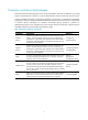
High availability overview 1B Because communication interruptions can seriously affect widely-deployed value-added services such as IPTV and video conference, basic network infrastructures must be able to provide high availability. The following are the effective ways to improve availability: • Increasing fault tolerance. • Speeding up fault recovery. • Reducing impact of faults on services.
MTTR = fault detection time + hardware replacement time + system initialization time + link recovery time + routing time + forwarding recovery time. A smaller value of each item means a smaller MTTR and a higher availability. High availability technologies 15B Increasing MTBF or decreasing MTTR can enhance the availability of a network. The high availability technologies described in this section meet the level 2 and level 3 high availability requirements in the aspect of decreasing MTTR.
Protection switchover technologies 74B Protection switchover technologies aim at recovering network faults. They back up hardware, link, routing, and service information for switchover in case of network faults to ensure continuity of network services. A single availability technology cannot solve all problems. You should use a combination of availability technologies, chosen on the basis of detailed analysis of network environments and user requirements, to enhance network availability.
Configuring VRRP 2B The interfaces that VRRP involves can be only Layer 3 Ethernet interfaces and subinterfaces, VLAN interfaces, and Layer 3 aggregate interfaces unless otherwise specified. VRRP cannot be configured on an interface of an aggregation group. The term "router" in this document refers to both routers and routing-capable firewalls and UTM devices.
Configuring a default route for network hosts facilitates your configuration, but also requires high performance stability of the device that acts as the gateway. Using more egress gateways is a common way to improve system reliability, but introduces the problem of routing among the egresses. Virtual Router Redundancy Protocol (VRRP) is designed to address this problem. VRRP adds a group of routers that can act as network gateways to a VRRP group, which forms a virtual router.
The router with the highest priority among the three routers is elected as the master to act as the gateway, and the other two are backups. The IP address of the virtual router can be either an unused IP address on the segment where the VRRP group resides or the IP address of an interface on a router in the VRRP group. In the latter case, the router is called the IP address owner. Only one IP address owner can be configured for a VRRP group.
VRRP preemption delay timer 2. To avoid frequent state changes among members in a VRRP group and provide the backups enough time to collect information (such as routing information), each backup waits for a period of time called the preemption delay time. The backup waits this period of time after it receives an advertisement with the priority lower than the local priority, then it sends VRRP advertisements to start a new master election in the VRRP group and becomes the master.
• Virtual Rtr ID (VRID)—ID of the virtual router. It ranges from 1 to 255. • Priority—Priority of the router in the VRRP group, in the range 0 to 255. A greater value represents a higher priority. • Count IP Addrs/Count IPv6 Addrs—Number of virtual IPv4 or IPv6 addresses for the VRRP group. A VRRP group can have multiple virtual IPv4 or IPv6 addresses. • Auth Type—Authentication type. 0 means no authentication, 1 means simple text authentication, and 2 means MD5 authentication.
of the master is automatically decreased by a specified value and a higher priority router in the VRRP group becomes the master. 2. Tracking a track entry By monitoring a track entry, you can do the following: { Monitor an uplink and change the priority of the router according to the uplink state. If the uplink fails, hosts in the LAN cannot access external networks through the router. The state of the monitored track entry is negative and the priority of the router decreases by a specified value.
Figure 6 VRRP in load sharing mode A router can be in multiple VRRP groups and hold a different priority in a different group. As shown in Figure 6, the following VRRP groups are present: 480H { VRRP group 1—Router A is the master. Router B and Router C are the backups. { VRRP group 2—Router B is the master. Router A and Router C are the backups. { VRRP group 3—Router C is the master. Router A and Router B are the backups.
Step Remarks Optional. 2. Configuring a VRRP group 482H Configure router priority, preemption mode, authentication mode, packet attributes, and tracking function of the VRRP group. Creating a VRRP group 76B 1. Select High Reliability > VRRP from the navigation tree. The VRRP interfaces page appears. Figure 7 VRRP interfaces page 2. Click the icon corresponding to the interface to be configured. The VRRP group page appears.
Figure 9 Creating a VRRP group 4. Enter the group number of the VRRP group (VRID). 5. Enter the virtual IP address of the VRRP group, and click Add to add the virtual IP address to the Virtual IP Members field. If the VRRP interface connects to multiple subnets, you can configure multiple virtual IP addresses for the VRRP group to implement router backup on different subnets. The virtual IP address cannot be all 0s (0.0.0.0), a broadcast address (255.255.255.
Figure 10 Modifying the VRRP group configuration 4. Configure the parameters as described in Table 4. 483H Table 4 Configuration items Item Description VRID Display group number of the VRRP group. Configure the virtual IP address of the VRRP group. If an interface connects to multiple subnets, you can configure multiple virtual IP addresses for the VRRP group to implement router backup on different subnets. IMPORTANT: • The virtual IP address cannot be 0.0.0.0, 255.255.255.
Item Description Set the priority of the routers in a VRRP group. The greater the value, the higher the priority. IMPORTANT: • VRRP determines the role (master or backup) of each router in the VRRP group by Priority priority. A router with a higher priority has more opportunity to become the master. • VRRP priority is in the range of 0 to 255. Priority 0 is reserved for special uses and priority 255 for the IP address owner. • When a router acts as the IP address owner, its priority is always 255.
Figure 11 Modifying the VRRP group configuration 6. Configure the parameters as described in Table 5. 7. Click Apply. 48H Table 5 Configuration items Item Description Object Configure the track object function by adding the Track object to be monitored and the processing method: • Object—Specify the serial number of the Track object to be monitored. You can specify an uncreated object.
Item Description Configure the track interface function by adding the specified interface to be monitored and the processing method. Interface • Interface—Name of the interface to be tracked. • Reduced Priority—If the monitored interface state turns from up to down, the priority of the router decreases by a specified value. Track Interface IMPORTANT: Reduced Priority • The configuration takes effect only when the router is not the IP address owner.
Specify the type of the MAC addresses mapped to the virtual IP addresses before creating a VRRP group. You cannot change the address mapping setting after a VRRP group is created. To specify the type of MAC addresses mapped to virtual IP addresses: Step Command Remarks 3. Enter system view. system-view N/A 4. Specify the type of MAC addresses mapped to virtual IP addresses. vrrp method { real-mac | virtual-mac } Optional. Virtual MAC address by default.
Step Command Remarks 1. Enter system view. system-view N/A 2. Enter the specified interface view. interface interface-type interface-number N/A 3. Create a VRRP group and configure a virtual IP address for the VRRP group. vrrp vrid virtual-router-id virtual-ip virtual-address VRRP group is not created by default. NOTE: The maximum number of VRRP groups on an interface and the maximum number of virtual IP addresses in a VRRP group are both 16.
Step Command Remarks Optional. 4. Configure the firewall in the VRRP group to operate in preemptive mode and configure preemption delay. vrrp vrid virtual-router-id preempt-mode [ timer delay delay-value ] The firewall in the VRRP group operates in preemptive mode and the preemption delay is 0 seconds by default. 5. Configure the interface to be tracked. vrrp vrid virtual-router-id track interface interface-type interface-number [ reduced priority-reduced ] Optional. 6.
Step Command Remarks 4. Configure the time interval for the master in the VRRP group to send VRRP advertisements. vrrp vrid virtual-router-id timer advertise adver-interval Optional. 1 second by default. Optional. 5. Disable TTL check on VRRP packets. By default, TTL check on VRRP packets is enabled. vrrp un-check ttl You do not need to create a VRRP group before executing this command.
VRRP for IPv6 configuration task list 85B Task Remarks Specifying the type of MAC addresses mapped to virtual IPv6 addresses Optional. Creating a VRRP group and configuring a virtual IPv6 address Required. Configuring router priority, preemptive mode and tracking function Optional. Configuring VRRP packet attributes Optional.
Configuration prerequisites 241B Before creating a VRRP group and configuring a virtual IPv6 address on an interface, configure an IPv6 address for the interface and make sure that it is in the same network segment as the virtual IPv6 address to be configured.
Configuration guidelines 245B • The running priority of an IP address owner is always 255 and you do not need to configure it. An IP address owner always operates in preemptive mode. • Interface tracking is not configurable on an IP address owner. • If you configure an interface to be tracked or a track entry to be monitored on a firewall that is the IP address owner in a VRRP group, the configuration does not take effect.
Configuration guidelines 248B • You might configure different authentication modes and authentication keys for the VRRP groups on an interface. However, the members of the same VRRP group must use the same authentication mode and authentication key. • Excessive traffic might cause a backup to trigger a change of its status because the backup does not receive any VRRP advertisements for a specified period of time. To solve this problem, prolong the time interval to send VRRP advertisements.
IPv4 VRRP configuration examples 2B Single VRRP group configuration example (in the Web interface) 91B Network requirements 250B As shown in Figure 12, Host A wants to access Host B on the Internet, using 202.38.160.111/24 as its default gateway. Firewall A and Firewall B belong to VRRP group 1 with the virtual IP address 202.38.160.111/24. 49H If Firewall A operates properly, the packets that Host A sends to Host B are forwarded by Firewall A.
Figure 13 Creating VRRP group 1 3. Configure VRRP group attributes: a. On the VRRP group page of GigabitEthernet 0/1, click the group 1. icon corresponding to VRRP b. Enter 110 in the Priority field. c. Select Preemptive from the Preempt Mode field. d. Enter 5 in the Delay field. e. Select Simple from the Authentication field. f. Enter hello in the Key field. g. Enter 5 in the Advertise Time field. h. Click Display Track Config. i.
Figure 14 Configuring VRRP group attributes Configuring Firewall B 25B 1. Configure the IP address of each interface and the zones. (Details not shown) 2. Create VRRP group 1 on GigabitEthernet 0/1 and configure the virtual IP address as 202.38.160.111: a. Select High Availability > VRRP from the navigation tree. b. Click the icon corresponding to GigabitEthernet 0/1. The VRRP group page appears. c. Click Add. The page for creating a VRRP group appears. d. Enter 1 in the VRID field and 202.38.160.
Figure 15 Creating VRRP group 1 3. Configure VRRP group attributes: a. On the VRRP group page of GigabitEthernet 0/1, click the group 1. icon corresponding to VRRP b. Select Preemptive from the Preempt Mode field. c. Enter 5 in the Delay field. d. Select Simple from the Authentication field. e. Enter hello in the Key field. f. Enter 5 in the Advertise Time field. g. Click Apply.
Single VRRP group configuration example (at the CLI) 92B Network requirements 254B • Host A needs to access Host B on the Internet, using 202.38.160.111/24 as its default gateway. • Firewall A and Firewall B belong to VRRP group 1 with the virtual IP address of 202.38.160.111/24. • If Firewall A operates normally, packets sent from Host A to Host B are forwarded by Firewall A. If Firewall A fails, packets sent from Host A to Host B are forwarded by Firewall B.
3. Verify the configuration: After the configuration, Host B can be pinged successfully on Host A. To verify your configuration, use the display vrrp verbose command. # Display the detailed information about VRRP group 1 on Firewall A.
Preempt Mode : Yes Auth Type : None Delay Time Virtual IP : 202.38.160.111 Virtual MAC : 0000-5e00-0101 Master IP : 202.38.160.2 : 5 The output shows that if Firewall A fails, Firewall B becomes the master, and packets sent from host A to host B are forwarded by Firewall B. # After Firewall A resumes normal operation, use the display vrrp verbose command to display the detailed information about VRRP group 1 on Firewall A.
Figure 18 Network diagram Configuration procedure 257B 1. Configure Firewall A: system-view [FirewallA] interface gigabitethernet 0/1 [FirewallA-GigabitEthernet0/1] ip address 202.38.160.1 255.255.255.0 # Create VRRP group 1 and configure its virtual IP address as 202.38.160.111. [FirewallA-GigabitEthernet0/1] vrrp vrid 1 virtual-ip 202.38.160.
[FirewallB-GigabitEthernet0/1] vrrp vrid 1 authentication-mode simple hello # Configure the master to send VRRP packets every four seconds. [FirewallB-GigabitEthernet0/1] vrrp vrid 1 timer advertise 4 # Configure Firewall B to operate in preemptive mode, so that Firewall B can become the master after the priority of Firewall A decreases to a value lower than 100. Configure the preemption delay as five seconds to avoid frequent status switchover.
# If interface GigabitEthernet 0/2 on Firewall A is not available, the detailed information about VRRP group 1 on Firewall A is displayed.
Figure 19 Network diagram Configuring Firewall A 259B 1. Configure the IP address of each interface and the zones. (Details not shown.) 2. Create VRRP group 1 on GigabitEthernet 0/1 and configure the virtual IP address as 202.38.160.111: a. Select High Availability > VRRP from the navigation tree. b. Click the icon corresponding to GigabitEthernet 0/1. The VRRP group page appears. c. Click Add. The page for creating a VRRP group appears. d. Enter 1 in the VRID field and 202.38.160.
c. Click Apply. Figure 21 Creating VRRP group 2 4. Set the priority of Firewall A in VRRP group 1 to 110: a. On the VRRP group page of GigabitEthernet 0/1, click the icon corresponding to VRRP group 1. b. Enter 110 in the Priority field. c. Click Apply. Figure 22 Setting the priority of Firewall A in VRRP group 1 Configuring Firewall B 260B The Web interfaces for configuring Firewall B are similar to those when you configure Firewall A. The figures are omitted. 1.
The page for creating a VRRP group appears. d. Enter 1 in the VRID field and 202.38.160.111 in the Virtual IP field, and click Add to add the virtual IP address to the Virtual IP Members field. e. Click Apply. 3. Create VRRP group 2 on GigabitEthernet 0/1 and configure the virtual IP address as 202.38.160.112: a. On the VRRP group page of GigabitEthernet 0/1, click Add. b. Enter 2 in the VRID field and 202.38.160.
Figure 23 Network diagram Configuration procedure 263B 1. Configure Firewall A: system-view [FirewallA] interface gigabitethernet0/1 [FirewallA-GigabitEthernet0/1] ip address 202.38.160.1 255.255.255.0 # Create VRRP group 1 and configure its virtual IP address as 202.38.160.111. [FirewallA-GigabitEthernet0/1] vrrp vrid 1 virtual-ip 202.38.160.
Run Mode : Standard Run Method : Virtual MAC Total number of virtual routers : 2 Interface GigabitEthernet0/1 VRID : 1 Adver Timer : 1 Admin Status : Up State : Master Config Pri : 110 Running Pri : 110 Preempt Mode : Yes Delay Time : 0 Auth Type : None Virtual IP : 202.38.160.111 Virtual MAC : 0000-5e00-0101 Master IP : 202.38.160.
The output shows that in VRRP group 1 Firewall A is the master, Firewall B is the backup and the host with the default gateway of 202.38.160.111/24 accesses the Internet through Firewall A. In VRRP group 2 Firewall A is the backup, Firewall B is the master and the host with the default gateway of 202.38.160.112/24 accesses the Internet through Firewall B. NOTE: To implement load balancing between the VRRP groups, be sure to configure the default gateway as 202.38.160.111 or 202.38.160.
[FirewallA-GigabitEthernet0/1] vrrp ipv6 vrid 1 virtual-ip 1::10 # Configure the priority of Firewall A in VRRP group 1 as 110, which is higher than that of Firewall B (100), so that Firewall A can become the master. [FirewallA-GigabitEthernet0/1] vrrp ipv6 vrid 1 priority 110 # Configure Firewall A to operate in preemptive mode so that it can become the master whenever it works normally; configure the preemption delay as five seconds to avoid frequent status switchover.
Run Mode : Standard Run Method : Virtual MAC Total number of virtual routers : 1 Interface GigabitEthernet0/1 VRID : 1 Adver Timer : 100 Admin Status : Up State : Backup Config Pri : 100 Running Pri : 100 Preempt Mode : Yes Delay Time : 5 Become Master : 4200ms left Auth Type : None Virtual IP : FE80::10 1::10 Master IP : FE80::1 The output shows that in VRRP group 1 Firewall A is the master, Firewall B is the backup and packets sent from Host A to Host B are forwarded by Firewal
Virtual IP : FE80::10 1::10 Virtual MAC : 0000-5e00-0201 Master IP : FE80::1 The output shows that after Firewall A resumes normal operation, it becomes the master, and packets sent from Host A to Host B are forwarded by Firewall A. VRRP interface tracking configuration example 97B Network requirements 26B • Firewall A and Firewall B belong to VRRP group 1 with the virtual IPv6 addresses of 1::10/64 and FE80::10.
# Configure the priority of Firewall A in VRRP group 1 as 110, which is higher than that of Firewall B (100), so that Firewall A can become the master. [FirewallA-GigabitEthernet0/1] vrrp ipv6 vrid 1 priority 110 # Set the authentication mode of VRRP group 1 as simple and authentication key to hello. [FirewallA-GigabitEthernet0/1] vrrp ipv6 vrid 1 authentication-mode simple hello # Set the interval on Firewall A for sending VRRP advertisements to 400 centiseconds.
Interface GigabitEthernet0/1 VRID : 1 Adver Timer : 400 Admin Status : Up State : Master Config Pri : 110 Running Pri : 110 Preempt Mode : Yes Delay Time : 5 Auth Type : Simple Key : hello Virtual IP : FE80::10 1::10 Virtual MAC : 0000-5e00-0201 Master IP : FE80::1 VRRP Track Information: Track Interface: GE0/2 State : Up Pri Reduced : 30 # Display the detailed information about VRRP group 1 on Firewall B.
1::10 Master IP : FE80::2 VRRP Track Information: Track Interface: GE0/2 State : Down Pri Reduced : 30 # When interface GigabitEthernet 0/2 on Firewall A fails, display the detailed information about VRRP group 1 on Firewall B.
Figure 26 Network diagram Virtual IPv6 address 2: Virtual IP address 1: FE80::20 FE80::10 1::20/64 1::10/64 Gateway: 1::10/64 GE0/1 FE80::1 1::1/64 Host A Firewall A Gateway: 1::20/64 Internet GE0/1 FE80::2 1::2/64 Host B Gateway: 1::20/64 Firewall B Host C Configuration procedure 269B 1.
# Set the priority of Firewall B in VRRP group 2 to 110, which is higher than that of Firewall A (100), so that Firewall B can become the master in VRRP group 2. [FirewallB-GigabitEthernet0/1] vrrp ipv6 vrid 2 priority 110 3. Verify the configuration: To verify your configuration, use the display vrrp ipv6 verbose command. # Display the detailed information about the VRRP group on Firewall A.
Master IP : FE80::1 Interface GigabitEthernet0/1 VRID : 2 Adver Timer : 100 Admin Status : Up State : Master Config Pri : 110 Running Pri : 110 Preempt Mode : Yes Delay Time : 0 Auth Type : None Virtual IP : FE80::20 1::20 Virtual MAC : 0000-5e00-0202 Master IP : FE80::2 The output shows that in VRRP group 1, Firewall A is the master, Firewall B is the backup, and the host with the default gateway of 1::10/64 access the Internet through Firewall A.
Solution 275B Ping between these masters, and do the following: • If the ping fails, check network connectivity. • If the ping succeeds, check that their configurations are consistent in terms of number of virtual IP addresses, virtual IP addresses, advertisement interval, and authentication. Frequent VRRP state transition 10B Symptom 276B Frequent VRRP state transition. Analysis 27B The VRRP advertisement interval is set too short.
Configuring stateful failover 3B The term "router" in this document refers to both routers and routing-capable firewalls and UTM devices.
2. The two devices exchange state negotiation messages periodically through the failover link. After the two devices enter the synchronized state, they back up the sessions of each other to make sure that the sessions on them are consistent. 3. If one device fails, the other device can take over the services by using VRRP or a dynamic routing protocol (such as OSPF) to avoid service interruption. The stateful failover feature supports backing up NAT, ALG, blacklist, ASPF, and IPsec services.
• Silence—The device has just started, or is transiting from synchronization state to independence state. • Independence—The silence timer has expired, but no failover link is established. • Synchronization—The device has completed state negotiation with the other device and is ready for service backup.
• An intermediary device (such as a router, a switch, or a hub) is allowed between the failover interfaces. Make sure the packets forwarded by the intermediary device carry the backup VLAN tag. • Do not directly connect two failover interfaces on the same stateful failover device. Configuring stateful failover in the Web interface 28B Configuring stateful failover 106B 1. Select High Reliability > Stateful Failover from the navigation tree. The stateful failover configuration page appears.
Item Description Enable/disable the session failover function. Session Failover IMPORTANT: To enable stateful failover for NAT, ALG, and ASPF services, you must enable session failover. Enable/disable the IPsec failover function. IPSec Failover IMPORTANT: To enable stateful failover for IPsec services, you must enable IPsec failover. Select whether to support asymmetric path. • Select the Asymmetric Path box if sessions enter and leave the internal network through one device.
Item Description Specify the backup VLAN. Backup VLAN Backup VLAN is specific to stateful failover. After you specify a backup VLAN, each device sends stateful failover packets carrying the backup VLAN tag and judges whether a packet is a stateful over packet based on the backup VLAN tag. IMPORTANT: HP does not recommend that you configure other services for the backup VLAN; otherwise, the operation of stateful failover may be affected.
Figure 31 Network diagram Internet GE0/3 GE0/3 VLAN 4001 GE0/1 GE0/1 Firewall A Firewall B Failover link GE0/2 GE0/2 Internal network Host A Host B Configuring Firewall A 280B 1. Configure failover interfaces: a. Select High Reliability > Stateful Failover from the navigation tree. b. Click Modify Backup Interface. The Backup Interface Configuration page appears. c. Select GigabitEthernet0/1 from the Optional Backup Interface(s) list, and click the << button. d. Click Apply.
d. Click Apply. Figure 33 Configuring stateful failover Configuring Firewall B 281B Except the Main Device for Configuration Synchronization and Auto Synchronization settings that are not needed for Firewall B, other settings on Firewall B are consistent with those on Firewall A and are not shown.
Task Remarks Optional. A device providing NAT, ALG, or blacklist services automatically backs up related information to the backup device after the configurations take effect. Service module related configurations Enabling stateful failover 109B When you enable stateful failover with the dhbk enable backup-type { dissymmetric-path | symmetric-path } command, one of the following happens: • If you specify the dissymmetric-path keyword, the two devices operate in active/active mode.
Configuring a failover interface and a backup VLAN 1B Failover interfaces send and receive stateful failover packets for data backup. Stateful failover packets are identified by the backup VLAN. Each stateful failover device adds the backup VLAN tag to the stateful failover packets, and sends the packets through the failover interface. Only the packets that are received from failover interfaces and carry the backup VLAN tag are treated as stateful failover packets.
Figure 34 Network diagram Internet VLAN 100 VLAN 100 VLAN 100 GE0/1 GE1/1 GE1/2 GE1/2 GE1/2 Failover Link Firewall A GE1/1 GE0/1 Failover Link Device A Device B Firewall B Internat network Configuration procedure 283B 1. Configure Firewall A: # Create VLAN 100. system-view [FirewallA] vlan 100 # Assign GigabitEthernet 0/1 to VLAN 100. [FirewallA-vlan100] port gigabitethernet 0/1 [FirewallA-vlan100] quit # Specify VLAN 100 as a backup VLAN.
Configuring IPC 4B IPC can be configured only at the CLI. This chapter provides an overview of IPC and describes the IPC monitoring commands. Overview 30B Inter-Process Communication (IPC) provides a reliable communication mechanism among processing units, typically CPUs. This section describes the basic IPC concepts. Node 14B An IPC node is an independent IPC-capable processing unit, typically, a CPU. The device is a centralized device that has only one CPU.
C ha nn el 2 Figure 35 Relationship between a node, link and channel Link Packet sending modes 17B IPC uses one of the following modes to send packets for upper layer application modules: • Unicast—One node sends packets to another node. • Multicast—One node sends packets to several other nodes. This mode includes broadcast, a special multicast. To use multicast mode, an application module must create a multicast group that includes a set of nodes.
Displaying and maintaining IPC 32B Task Command Remarks Display IPC node information. display ipc node [ | { begin | exclude | include } regular-expression ] Available in any view. Display channel information for a node. display ipc channel { node node-id | self-node } [ | { begin | exclude | include } regular-expression ] Available in any view. Display queue information for a node.
Configuring track 5B Track can be configured only at the CLI. Track overview 3B The track module works between application and detection modules, as shown in Figure 36. It shields the differences between various detection modules from application modules. 504H Collaboration is enabled after you associate the track module with a detection module and an application module.
• NQA. • BFD. • Interface management module. Collaboration between the track module and an application module 285B After being associated with an application module, when the status of the track entry changes, the track module notifies the application module, which then takes proper actions. The following application modules can be associated with the track module: • VRRP. • Static routing. • Policy-based routing. • Interface backup.
Task Remarks Associating track with NQA Required. Associating track with BFD Use one of the approaches. 508H Associating the track module with a detection module 507H 509H Associating track with interface management 510H Associating track with VRRP 512H Associating track with static routing Associating the track module with an application module Required. 513H 51H Associating track with PBR 514H Use one of the approaches.
Hardware Feature compatible F1000-A-EI/F1000-S-EI No F1000-E No F5000 Yes Firewall module No U200-A No U200-S No BFD supports the control packet mode and echo packet mode: • Associating a track entry with the echo-mode BFD session detects a directly connected link. Before that, you must configure the source IP address of BFD echo packets. • Associating a track entry with the control-mode BFD session detects an indirectly connected link.
When the physical or network-layer protocol status of the interface changes to down, the interface management module informs the track module of the change and the track module sets the track entry to Negative. • To associate track with interface management: Step 1. Enter system view. Command Remarks system-view N/A • Create a track entry, associate it with the interface 2. Associating track with interface management.
Monitor the master on a backup. If a fault occurs on the master, the backup working in switchover mode will switch to the master immediately to maintain normal communication. • Follow these guidelines when you associate track with VRRP: • VRRP tracking is not valid on an IP address owner. An IP address owner refers to a router when the IP address of the virtual router is the IP address of an interface on the router in the VRRP group.
• You can associate a nonexistent track entry with a static route. The association takes effect only after you use the track command to create the track entry. • If the track module detects the next hop accessibility of the static route in a private network through NQA, the VPN instance name of the next hop of the static route must be consistent with that configured for the NQA test group. Otherwise, accessibility detection cannot function properly.
The following objects can be associated with a track entry: • Outgoing interface. • Next hop. • Default outgoing interface. • Default next hop. Configuration prerequisites 287B Before you associate track with PBR, create a policy or a policy node and configure the match criteria as well. Configuration procedure 28B You can associate a nonexistent track entry with PBR. The association takes effect only after you use the track command to create the track entry.
Associating track with interface backup 126B Interface backup allows interfaces on a device to back up each other, with the active interface transmitting data and the standby interfaces staying in backup state. When the active interface or the link where the active interface resides fails, and data cannot be transmitted, a standby interface is brought up to transmit data, enhancing the reliability of the network.
Network requirements 289B • As shown in Figure 37, configure Host A to access Host B on the Internet. The default gateway of Host A is 10.1.1.10/24. • Firewall A and Firewall B belong to VRRP group 1, which has the virtual IP address 10.1.1.10. • When Firewall A works normally, packets from Host A to Host B are forwarded through Firewall A. When NQA detects that a fault is on the uplink of Firewall A, packets from Host A to Host B are forwarded through Firewall B.
4. Configure VRRP on Firewall A: # Create VRRP group 1, and configure the virtual IP address 10.1.1.10 for the group. [FirewallA] interface gigabitethernet0/1 [FirewallA-GigabitEthernet0/1] vrrp vrid 1 virtual-ip 10.1.1.10 # Set the priority of Firewall A in VRRP group 1 to 110. [FirewallA-GigabitEthernet0/1] vrrp vrid 1 priority 110 # Set the authentication mode of VRRP group 1 to simple, and the authentication key to hello.
VRRP Track Information: Track Object : 1 State : Positive Pri Reduced : 30 # Display detailed information about VRRP group 1 on Firewall B.
Admin Status : Up State : Master Config Pri : 100 Running Pri : 100 Preempt Mode : Yes Delay Time : 5 Auth Type : Simple Key : hello Virtual IP : 10.1.1.10 Virtual MAC : 0000-5e00-0101 Master IP : 10.1.1.2 The output shows that when a fault is on the link between Firewall A and Router A, the priority of Firewall A decreases to 80. Firewall A becomes the backup, and Firewall B becomes the master. Packets from Host A to Host B are forwarded through Firewall B.
Figure 38 Network diagram Configuration procedure 293B 1. Configure VRRP on Firewall A: system-view [FirewallA] interface gigabitethernet 1/1 # Create VRRP group 1, and configure the virtual IP address 192.168.0.10 for the group. Set the priority of Firewall A in VRRP group 1 to 110. [FirewallA-gigabitethernet1/1] vrrp vrid 1 virtual-ip 192.168.0.10 [FirewallA-gigabitethernet1/1] vrrp vrid 1 priority 110 [FirewallA-gigabitethernet1/1] return 2.
[FirewallB-gigabitethernet1/1] vrrp vrid 1 virtual-ip 192.168.0.10 [FirewallB-gigabitethernet1/1] vrrp vrid 1 track 1 switchover [FirewallB-gigabitethernet1/1] return Verifying the configuration 294B # Display the detailed information of VRRP group 1 on Firewall A.
Local IP : 192.168.0.102 The output shows that when the status of the track entry becomes Positive, Firewall A is the master, and Firewall B the backup. # Enable VRRP state debugging and BFD event debugging on Firewall B. terminal debugging terminal monitor debugging vrrp state debugging bfd event # When Firewall A fails, the following output is displayed on Firewall B. *Dec 17 14:44:34:142 2008 FirewallB BFD/7/EVENT:Send sess-down Msg, [Src:192.168.0.
Network requirements 295B • As shown in Figure 39, Firewall A and Firewall B belong to VRRP group 1, whose virtual IP address is 192.168.0.10. • The default gateway of the hosts in the LAN is 192.168.0.10. • When Firewall A works normally, hosts in the LAN access the external network through Firewall A.
[FirewallA] interface gigabitethernet 1/2 [FirewallA-gigabitethernet 1/2] vrrp vrid 1 virtual-ip 192.168.0.10 [FirewallA-gigabitethernet 1/2] vrrp vrid 1 priority 110 [FirewallA-gigabitethernet 1/2] vrrp vrid 1 track 1 reduced 20 [FirewallA-gigabitethernet 1/2] return 4. Configure VRRP on Firewall B: # Create VRRP group 1, and configure the virtual IP address of the group as 192.168.0.10.
Interface gigabitethernet 1/2 VRID : 1 Adver Timer : 1 Admin Status : Up State : Backup Config Pri : 100 Running Pri : 100 Preempt Mode : Yes Delay Time : 0 Become Master : 2200ms left Auth Type : None Virtual IP : 192.168.0.10 Master IP : 192.168.0.101 The output shows that when the status of track entry 1 becomes Positive, Firewall A is the master and Firewall B the backup. # When the uplink of Firewall A goes down, the status of track entry 1 becomes Negative.
Admin Status : Up State : Master Config Pri : 100 Running Pri : 100 Preempt Mode : Yes Delay Time : 0 Auth Type : None Virtual IP : 192.168.0.10 Virtual MAC : 0000-5e00-0101 Master IP : 192.168.0.102 The output shows that when Firewall A detects that the uplink fails through BFD, it decreases its priority by 20 to make sure that Firewall B can preempt as the master.
Figure 40 Network diagram Configuration procedure 29B 1. Configure the IP address of each interface as shown in Figure 40. (Details not shown.) 2. Configure Firewall A: 521H # Configure a static route to 30.1.1.0/24, with the address of the next hop as 10.1.1.2 and the default priority 60. This static route is associated with track entry 1. system-view [FirewallA] ip route-static 30.1.1.0 24 10.1.1.2 track 1 # Configure a static route to 30.1.1.
[FirewallA] nqa schedule admin test start-time now lifetime forever # Configure track entry 1, and associate it with reaction entry 1 of the NQA test group (with the administrator admin, and the operation tag test). [FirewallA] track 1 nqa entry admin test reaction 1 3. Configure Router A: # Configure a static route to 30.1.1.0/24, with the address of the next hop as 10.2.1.4. system-view [RouterA] ip route-static 30.1.1.0 24 10.2.1.4 # Configure a static route to 20.1.1.
# Configure track entry 1, and associate it with reaction entry 1 of the NQA test group (with the administrator admin, and the operation tag test). [FirewallB] track 1 nqa entry admin test reaction 1 Verifying the configuration 30B # Display information of the track entry on Firewall A.
Routing Tables: Public Destinations : 10 Destination/Mask Proto 10.1.1.0/24 Routes : 10 Pre Cost NextHop Interface Direct 0 0 10.1.1.1 GE0/2 10.1.1.1/32 Direct 0 0 127.0.0.1 InLoop0 10.2.1.0/24 Static 60 0 10.1.1.2 GE0/2 10.3.1.0/24 Direct 0 0 10.3.1.1 GE0/3 10.3.1.1/32 Direct 0 0 127.0.0.1 InLoop0 20.1.1.0/24 Direct 0 0 20.1.1.1 GE0/1 20.1.1.1/32 Direct 0 0 127.0.0.1 InLoop0 30.1.1.0/24 Static 80 0 10.3.1.3 GE0/3 127.0.0.0/8 Direct 0 0 127.0.0.
VRRP-track-interface management collaboration configuration example 13B In this example, the master monitors the uplink interface. Network requirements 301B • As shown in Figure 41, Host A needs to access Host B on the Internet. The default gateway of Host A is 10.1.1.10/24. • Firewall A and Firewall B belong to VRRP group 1, whose virtual IP address is 10.1.1.10. • When Firewall A works properly, packets from Host A to Host B are forwarded through Firewall A.
# Create VRRP group 1, and configure the virtual IP address 10.1.1.10 for the group. [FirewallB-GigabitEthernet0/1] vrrp vrid 1 virtual-ip 10.1.1.10 Verifying the configuration 30B After configuration, ping Host B on Host A, and you can see that Host B is reachable. Use the display vrrp command to view the configuration result. # Display detailed information about VRRP group 1 on Firewall A.
[FirewallA-GigabitEthernet0/2] display vrrp verbose IPv4 Standby Information: Run Mode : Standard Run Method : Virtual MAC Total number of virtual routers : 1 Interface GigabitEthernet0/1 VRID : 1 Adver Timer : 1 Admin Status : Up State : Backup Config Pri : 110 Running Pri : 80 Preempt Mode : Yes Delay Time : 0 Become Master : 2200ms left Auth Type : None Virtual IP : 10.1.1.10 Master IP : 10.1.1.
Configuring a collaboration group 6B Overview 39B You can add ports on a device to one group called "collaboration group." All ports in the group have consistent state. They are either able or unable to forward packets at the same time. Collaboration group is mainly used to trigger the downlink port state based on the uplink port state, and implement fast link switchover. As shown in Figure 42, LAN users Host A, Host B and Host C access the Internet through Device B.
Configuring a collaboration group in the web interface 40B Assigning interfaces to a collaboration group 132B By default, 24 collaboration groups numbered from 1 to 24 exist in the system, and the groups do not contain any interface. To assign interfaces to a collaboration group: 1. Select High Reliability > Collaboration Group from the navigation tree. The page for displaying collaboration groups appears. Figure 43 Managing collaboration groups 2. Click the icon for a collaboration group.
Figure 44 Configuring a collaboration group 3. Select the boxes of interfaces to be assigned to the collaboration group. The number of interfaces assigned to the collaboration group must be no more than the maximum supported interface number displayed on the page. 4. Click Apply. When you assign interfaces to a collaboration group, follow these guidelines: • A port can belong to only one collaboration group.
The selected interfaces are the member interfaces of the collaboration group. The interfaces can be in one of the following states: { Up—The interface is physically up. { Down—The interface is physically down. { Linkgroup-down—The interface is forcibly shut down by the collaboration group and cannot transmit packets. Collaboration group configuration example 134B Network requirements 304B As shown in Figure 45, LAN users Host A, Host B, and Host C access the Internet through Firewall A.
Figure 46 Assigning GigabitEthernet 0/1 and GigabitEthernet 0/2 to Collaboration Group 1 Verifying the configuration 306B 1. Remove the cable connecting Device to GigabitEthernet 0/2 on Firewall A. 2. Select High Reliability > Collaboration Group from the navigation tree of Firewall A, and check the status of Collaboration Group 1. The page that appears shows that the status of Collaboration Group 1 is down. Figure 47 Checking the status of Collaboration Group 1 3.
Figure 48 Checking the status of Collaboration Group 1's member ports Configuring a collaboration group at the CLI 41B Configuring a collaboration group 135B Perform the following operation on multiple interfaces to add them to a collaboration group. An interface can belong to only one collaboration group. A collaboration group can have at most eight interfaces. When a device is connected to another device through multiple ports, do not assign these ports to the same collaboration group.
Collaboration group configuration example 137B Network requirements 307B As shown in Figure 49, LAN users Host A, Host B, and Host C access the Internet through Firewall A. Firewall B serves as a backup for Firewall A. Configure Firewall A so that when the link connecting Device and Firewall A goes down, the traffic rapidly switches from Firewall A to Firewall B.
Configuring NQA 7B NQA can be configured only at the CLI. Overview 42B Network quality analyzer (NQA) allows you to monitor link status, measure network performance, verify the service levels for IP services and applications, and troubleshoot network problems.
Figure 51 Collaboration The following describes how a static route destined for 192.168.0.88 is monitored through collaboration: 1. NQA monitors the reachability to 192.168.0.88. 2. When 192.168.0.88 becomes unreachable, NQA notifies the track module of the change. 3. The track module notifies the static routing module of the state change. 4. The static routing module sets the static route as invalid according to a predefined action.
NQA configuration task list 43B Complete the following task to configure the NQA server: Task Remarks Configuring the NQA server Required for NQA operations types of TCP, UDP echo, UDP jitter, and voice. 534H Complete these tasks to configure the NQA client: Task Remarks Enabling the NQA client Required. 53H Configuring an ICMP echo operation 536H Configuring a DHCP operation 537H Configuring a DNS operation 538H Configuring an FTP operation 539H Configuring an HTTP operation 540H Required.
To configure the NQA server: Step Command Remarks 1. Enter system view. system-view N/A 2. Enable the NQA server. nqa server enable Disabled by default. • Approach 1: 3. Configure a listening service. nqa server tcp-connect ip-address port-number Use at least one approach. • Approach 2: nqa server udp-echo ip-address port-number Configuring the NQA client 45B Enabling the NQA client 140B Step Command Remarks N/A 1. Enter system view. system-view 2. Enable the NQA client.
Step 5. 6. 7. Command Specify the payload size in each ICMP echo request. Configure the string to be filled in the payload of each ICMP echo request. Specify the VPN where the operation is performed. data-size size Remarks Optional. 100 bytes by default. Optional. data-fill string By default, the string is the hexadecimal number 00010203040506070809. Optional. vpn-instance vpn-instance-name By default, the operation is performed on the public network. Optional. • Approach 1: 8.
Step Command Specify an interface to perform the DHCP operation. 4. operation interface interface-type interface-number Remarks By default, no interface is specified to perform a DHCP operation. The specified interface must be up. Otherwise, no probe packets can be sent out. Configuring a DNS operation 143B A DNS operation measures the time the NQA client uses to translate a domain name into an IP address through a DNS server.
Step Command Remarks 1. Enter system view. system-view N/A 2. Create an NQA operation and enter NQA operation view. nqa entry admin-name operation-tag By default, no NQA operation is created. 3. Specify the FTP type and enter its view. type ftp N/A 4. Specify the IP address of the FTP server as the destination address of FTP request packets. destination ip ip-address By default, no destination IP address is configured. 5. Configure the source IP address of FTP request packets.
Step Command Remarks 3. Specify the HTTP type and enter its view. type http N/A 4. Configure the IP address of the HTTP server as the destination address of HTTP request packets. destination ip ip-address By default, no destination IP address is configured. Optional. 5. Configure the source IP address of request packets. By default, no source IP address is specified. source ip ip-address The source IP address must be the IP address of a local interface. The local interface must be up.
Step Command Remarks 1. Enter system view. system-view N/A 2. Create an NQA operation and enter NQA operation view. nqa entry admin-name operation-tag By default, no NQA operation is created. 3. Specify the UDP jitter type and enter its view. type udp-jitter N/A 4. Configure the destination address of UDP packets. By default, no destination IP address is configured. destination ip ip-address By default, no destination port number is configured. 5.
NOTE: The display nqa history command does not show the results of the UDP jitter operation. Use the display nqa result command to display the results, or use the display nqa statistics command to display the statistics of the operation. Configuring an SNMP operation 147B An SNMP operation measures the time the NQA client uses to get a value from an SNMP agent. To configure an SNMP operation: Step Command Remarks 1. Enter system view. system-view N/A 2.
Step 3. 4. 5. Specify the TCP type and enter its view. Configure the destination address of TCP packets. Configure the destination port of TCP packets. Command Remarks type tcp N/A By default, no destination IP address is configured. destination ip ip-address The destination address must be the same as the IP address of the listening service configured on the NQA server. By default, no destination port number is configured.
Step Command By default, no destination port number is configured. 5. Configure the destination port of UDP packets. destination port port-number 6. Configure the payload size in each UDP packet. data-size size 7. 8. Remarks The destination port number must be the same as that of the listening service on the NQA server. Optional. 100 bytes by default. Optional. Configure the string to be filled in the payload of each UDP packet. data-fill string Specify the source port of UDP packets.
The evaluation of voice quality depends on users' tolerance for voice quality, which you should consider. For users with higher tolerance for voice quality, use the advantage-factor command to configure the advantage factor. When the system calculates the ICPIF value, it substracts the advantage factor to modify ICPIF and MOS values, so both objective and subjective factors are considered. The voice operation requires both the NQA server and the NQA client.
Step Command Remarks Optional. 10. Configure the payload size in each voice packet. data-size size By default, the voice packet size depends on the codec type. The default packet size is 172 bytes for G.711A-law and G.711 μ-law codec type, and 32 bytes for G.729 A-law codec type. Optional. 11. Configure the string to be filled in the payload of each voice packet. data-fill string By default, the string is the hexadecimal number 00010203040506070809. 12.
Step Command Remarks Optional. Configure the source IP address of probe packets. 5. By default, no source IP address is specified. source ip ip-address The source IP address must be the IP address of a local interface. The local interface must be up. Otherwise, no probe packets can be sent out. Configuring optional parameters for an NQA operation 152B Unless otherwise specified, the following optional parameters apply to all NQA operation types.
Step Command Remarks Optional. 6. Specify the probe times. probe count times By default, an NQA operation performs one probe. The voice operation can perform only one probe, and does not support this command. Optional. 7. Specify the probe timeout time. probe timeout timeout By default, the timeout time is 3000 milliseconds. This setting is not available for the UDP jitter or voice operation. Optional. 8. 9. Specify the TTL for probe packets.
Step Command Remarks 5. Exit to system view. quit N/A 6. Associate track with NQA. See "Configuring track." N/A 7. Associate track with an application module. See "Configuring track." N/A Configuring threshold monitoring 154B Introduction 310B 1. Threshold types An NQA operation supports the following threshold types: { { { average—If the average value for the monitored performance metric either exceeds the upper threshold or goes below the lower threshold, a threshold violation occurs.
Configuration procedure 312B To configure threshold monitoring: Step Command Remarks 1. Enter system view. system-view N/A 2. Create an NQA operation and enter NQA operation view. nqa entry admin-name operation-tag By default, no NQA operation is created. Specify an NQA operation type and enter its view. type { dhcp | dlsw | dns | ftp | http | icmp-echo | snmp | tcp | udp-echo | udp-jitter | voice } N/A 3.
Step Command Remarks • Enable sending traps to the NMS when specified conditions are met: reaction trap { probe-failure consecutive-probe-failures | test-complete | test-failure cumulate-probe-failures } • Configure a reaction entry for monitoring the duration of an NQA operation (not supported in UDP jitter and voice operations): reaction item-number checked-element probe-duration threshold-type { accumulate accumulate-occurrences | average | consecutive consecutive-occurrences } threshold-value upper
Configuring the NQA statistics function 15B NQA collects statistics for an operation in a statistics group. To view information about the statistics groups, use the display nqa statistics command. To set the interval for collecting statistics, use the statistics interval command. If a new statistics group is to be saved when the number of statistics groups reaches the upper limit, the oldest statistics group is deleted.
To configure the history records saving function: Step Command Remarks 1. Enter system view. system-view N/A 2. Create an NQA operation and enter NQA operation view. nqa entry admin-name operation-tag By default, no NQA operation is created. 3. Enter NQA operation type view. type { dhcp | dlsw | dns | ftp | http | icmp-echo | snmp | tcp | udp-echo | udp-jitter | voice } N/A 4. Enable saving history records for the NQA operation.
Displaying and maintaining NQA 46B Task Command Remarks Display history records of NQA operations. display nqa history [ admin-name operation-tag ] [ | { begin | exclude | include } regular-expression ] Available in any view. Display the current monitoring results of reaction entries. display nqa reaction counters [ admin-name operation-tag [ item-number ] ] [ | { begin | exclude | include } regular-expression ] Available in any view. Display the result of the specified NQA operation.
Configuration procedure 314B # Assign each interface an IP address. (Details not shown.) # Configure static routes or a routing protocol to make sure the devices can reach each other. (Details not shown.) # Create an ICMP echo operation, and specify 10.2.2.2 as the destination IP address. system-view [Firewall] nqa entry admin test1 [Firewall-nqa-admin-test1] type icmp-echo [Firewall-nqa-admin-test1-icmp-echo] destination ip 10.2.2.2 # Configure 10.1.1.2 as the next hop.
Index Response Status Time 370 3 Succeeded 2011-08-23 15:00:01.2 369 3 Succeeded 2011-08-23 15:00:01.2 368 3 Succeeded 2011-08-23 15:00:01.2 367 5 Succeeded 2011-08-23 15:00:01.2 366 3 Succeeded 2011-08-23 15:00:01.2 365 3 Succeeded 2011-08-23 15:00:01.2 364 3 Succeeded 2011-08-23 15:00:01.1 363 2 Succeeded 2011-08-23 15:00:01.1 362 3 Succeeded 2011-08-23 15:00:01.1 361 2 Succeeded 2011-08-23 15:00:01.
Last succeeded probe time: 2011-11-22 09:54:03.8 Extended results: Packet loss in test: 0% Failures due to timeout: 0 Failures due to disconnect: 0 Failures due to no connection: 0 Failures due to sequence error: 0 Failures due to internal error: 0 Failures due to other errors: 0 Packet(s) arrived late: 0 # Display the history records of the DHCP operation.
[Firewall] nqa schedule admin test1 start-time now lifetime forever # Stop the DNS operation after a period of time. [Firewall] undo nqa schedule admin test1 # Display the results of the DNS operation. [Firewall] display nqa result admin test1 NQA entry (admin admin, tag test1) test results: Destination IP address: 10.2.2.2 Send operation times: 1 Receive response times: 1 Min/Max/Average round trip time: 62/62/62 Square-Sum of round trip time: 3844 Last succeeded probe time: 2008-11-10 10:49:37.
system-view [Firewall] nqa entry admin test1 [Firewall-nqa-admin-test1] type ftp # Specify the IP address of the FTP server 10.2.2.2 as the destination IP address. [Firewall-nqa-admin-test1-ftp] destination ip 10.2.2.2 # Specify 10.1.1.1 as the source IP address. [Firewall-nqa-admin-test1-ftp] source ip 10.1.1.1 # Set the FTP username to admin, and password to systemtest.
HTTP operation configuration example 162B Network requirements 321B As shown in Figure 56, configure an HTTP operation on the NQA client to test the time required to obtain data from the HTTP server. 561H Figure 56 Network diagram Configuration procedure 32B # Assign each interface an IP address. (Details not shown.) # Configure static routes or a routing protocol to make sure the devices can reach each other. (Details not shown.) # Create an HTTP operation.
Last succeeded probe time: 2011-11-22 10:12:47.9 Extended results: Packet loss in test: 0% Failures due to timeout: 0 Failures due to disconnect: 0 Failures due to no connection: 0 Failures due to sequence error: 0 Failures due to internal error: 0 Failures due to other errors: Packet(s) arrived late: 0 # Display the history records of the HTTP operation.
[FirewallA-nqa-admin-test1-udp-jitter] destination port 9000 # Configure the operation to repeat at an interval of 1000 milliseconds. [FirewallA-nqa-admin-test1-udp-jitter] frequency 1000 [FirewallA-nqa-admin-test1-udp-jitter] quit # Start the UDP jitter operation. [FirewallA] nqa schedule admin test1 start-time now lifetime forever # Stop the UDP jitter operation after a period of time. [FirewallA] undo nqa schedule admin test1 # Display the results of the UDP jitter operation.
# Display the statistics of the UDP jitter operation. [FirewallA] display nqa statistics admin test1 NQA entry (admin admin, tag test1) test statistics: NO. : 1 Destination IP address: 10.2.2.2 Start time: 2008-05-29 13:56:14.
Figure 58 Network diagram Configuration procedure 326B 1. Assign each interface an IP address. (Details not shown.) 2. Configure static routes or a routing protocol to make sure the devices can reach each other. (Details not shown.) 3. Configure the SNMP agent (Device): # Enable the SNMP agent, and set the SNMP version to all, the read community to public, and the write community to private.
Failures due to internal error: 0 Failures due to other errors: 0 Packet(s) arrived late: 0 # Display the history records of the SNMP operation. [Firewall] display nqa history admin test1 NQA entry (admin admin, tag test1) history record(s): Index Response Status Time 1 50 Timeout 2011-11-22 10:24:41.1 The output shows that Firewall uses 50 milliseconds to receive a response from the SNMP agent.
# Stop the TCP operation after a period of time. [FirewallA] undo nqa schedule admin test1 # Display the results of the TCP operation. [FirewallA] display nqa result admin test1 NQA entry (admin admin, tag test1) test results: Destination IP address: 10.2.2.2 Send operation times: 1 Receive response times: 1 Min/Max/Average round trip time: 13/13/13 Square-Sum of round trip time: 169 Last succeeded probe time: 2011-11-22 10:27:25.
[FirewallB] nqa server enable [FirewallB] nqa server udp-echo 10.2.2.2 8000 4. Configure Firewall A: # Create a UDP echo operation. system-view [FirewallA] nqa entry admin test1 [FirewallA-nqa-admin-test1] type udp-echo # Configure 10.2.2.2 as the destination IP address and port 8000 as the destination port. [FirewallA-nqa-admin-test1-udp-echo] destination ip 10.2.2.2 [FirewallA-nqa-admin-test1-udp-echo] destination port 8000 # Enable the saving of history records.
Figure 61 Network diagram Configuration procedure 32B 1. Assign each interface an IP address. (Details not shown.) 2. Configure static routes or a routing protocol to make sure the devices can reach each other. (Details not shown.) 3. Configure Firewall B: # Enable the NQA server, and configure a listening service to listen on IP address 10.2.2.2 and UDP port 9000. system-view [FirewallB] nqa server enable [FirewallB] nqa server udp-echo 10.2.2.2 9000 4.
Packet(s) arrived late: 0 Voice results: RTT number: 1000 Min positive SD: 1 Min positive DS: 1 Max positive SD: 204 Max positive DS: 1297 Positive SD number: 257 Positive DS number: 259 Positive SD sum: 759 Positive DS sum: 1797 Positive SD average: 2 Positive DS average: 6 Positive SD square sum: 54127 Positive DS square sum: 1691967 Min negative SD: 1 Min negative DS: 1 Max negative SD: 203 Max negative DS: 1297 Negative SD number: 255 Negative DS number: 259 Negative SD sum: 759 Negat
Positive SD number: 1030 Positive DS number: 1024 Positive SD sum: 4363 Positive DS sum: 5423 Positive SD average: 4 Positive DS average: 5 Positive SD square sum: 497725 Positive DS square sum: 2254957 Min negative SD: 1 Min negative DS: 1 Max negative SD: 360 Max negative DS: 1297 Negative SD number: 1028 Negative DS number: 1022 Negative SD sum: 1028 Negative DS sum: 1022 Negative SD average: 4 Negative DS average: 5 Negative SD square sum: 495901 Negative DS square sum: 5419 One way
[Firewall] nqa schedule admin test1 start-time now lifetime forever # Stop the DLSw operation after a period of time. [Firewall] undo nqa schedule admin test1 # Display the results of the DLSw operation. [Firewall] display nqa result admin test1 NQA entry (admin admin, tag test1) test results: Destination IP address: 10.2.2.2 Send operation times: 1 Receive response times: 1 Min/Max/Average round trip time: 19/19/19 Square-Sum of round trip time: 361 Last succeeded probe time: 2011-11-22 10:40:27.
2. On Firewall, configure a unicast static route, and associate the static route with a track entry: # Configure a static route, and associate the static route with track entry 1. system-view [Firewall] ip route-static 10.1.1.2 24 10.2.1.1 track 1 3. On Firewall, configure an ICMP echo operation: # Create an NQA operation with the administrator name being admin and operation tag being test1. [Firewall] nqa entry admin test1 # Configure the NQA operation type as ICMP echo.
127.0.0.1/32 Direct 0 0 127.0.0.1 InLoop0 The output shows that the static route with the next hop 10.2.1.1 is active, and the status of the track entry is positive. # Remove the IP address of GigabitEthernet 0/1 on Device A. system-view [DeviceA] interface gigabitethernet 0/1 [DeviceA-GigabitEthernet0/1] undo ip address # On Firewall, display information about all track entries.
Configuring Ethernet link aggregation 8B Overview 48B Ethernet link aggregation, or simply link aggregation, combines multiple physical Ethernet ports into one logical link called an "aggregate link." Link aggregation delivers the following benefits: • Increases bandwidth beyond the limits of any single link. In an aggregate link, traffic is distributed across the member ports. • Improves link reliability. The member ports dynamically back up one another.
Removing an aggregate interface also removes the corresponding aggregation group. At the same time, all member ports leave the aggregation group. When a Selected port fails, an Unselected port may become a Selected port and forward user traffic. Aggregation states of member ports in an aggregation group 39B A member port in an aggregation group can be in either of the following aggregation states: • Selected—A Selected port can forward user traffic.
aggregation group, see "Selecting a reference port" in the section "Aggregating links in static mode." For information about how a reference port is selected in a dynamic link aggregation group, see "Selecting a reference port" in the section "Aggregating links in dynamic mode." 571H 572H 573H 574H Link aggregation modes 34B Link aggregation can be done in dynamic mode or static mode. Dynamic link aggregation uses the IEEE 802.3ad LACP, but static link aggregation does not.
Table 10 LACP priorities Type Description Used by two peer devices (or systems) to determine which one is superior in link aggregation. System LACP priority In dynamic link aggregation, the system with higher system LACP priority sets the Selected state of member ports on its side first, and then the system with lower priority sets the port state accordingly. Port aggregation priority Determines the likelihood of a member port to be selected on a system.
Figure 65 Setting the aggregation state of a member port in a static aggregation group Set the aggregation state of a member port Yes Is there any hardware restriction? No No Is the port up? Yes Port attribute/class 2 configurations same as the reference port? No Yes More candidate ports than max.
Figure 66 Setting the state of a member port in a dynamic aggregation group Meanwhile, the system with the higher system ID, which has identified the aggregation state changes on the remote system, sets the aggregation state of local member ports as the same as their peer ports.
You can choose one or any combination of the following criteria for load sharing: • Source/Destination service port numbers • Source/Destination IP addresses • Protocol numbers You can also load balance traffic on a per-packet basis. Configuration restrictions and guidelines 49B Follow these guidelines when you configure a link aggregation group: • To ensure stable aggregation state and service continuity, do not change port attributes or class-two configurations on any member port.
Figure 67 Creating a static link aggregation group 3. Enter an ID for the Layer 2 link aggregation group to be created, which identifies both the Layer 2 aggregate interface and Layer 2 aggregation group. 4. Select one or multiple ports to be assigned to the link aggregation group from the chassis front panel. 5. Click Apply. Displaying information about a Layer 2 aggregate interface 175B Select Network > Link Aggregation from the navigation tree. 1. The Summary tab is displayed by default.
Figure 68 Displaying information about an aggregate interface Table 11 Field description Field Aggregation interface Description Type and ID of the aggregate interface. Bridge-Aggregation indicates a Layer 2 aggregate interface. Link Type Type of the aggregate interface. Partner ID ID of the remote device, including its LACP priority and MAC address. Selected Ports Number of Selected ports in each link aggregation group. (Only Selected ports can transmit and receive user data.
Network requirements 349B As shown in Figure 69, aggregate the ports on Device A and Device B to form a static link aggregation group, enhancing link reliability. 578H Figure 69 Network diagram Configuration procedure 350B 1. Create static link aggregation group 1 on Device A: a. Select Network > Link Aggregation from the navigation tree. b. Click Create to enter the page as shown in Figure 70. 579H c. Set the link aggregation interface ID to 1.
Figure 70 Creating static link aggregation group 1 2. Create static link aggregation group 1 on Device B. The configuration procedure is similar to that for Device A. (Details not shown.) Verifying the configuration 351B To view information about Layer 2 static aggregate interface 1 on Device A: 1. Select Network > Link Aggregation from the navigation tree. The Summary tab appears. 2. Select aggregate interface Bridge-Aggregation1 from the list on the upper part, as shown in Figure 71.
Figure 71 Configuration result Selected Selected Selected Configuring Ethernet link aggregation at the CLI 51B Ethernet link aggregation configuration task list 17B Task Remarks Configuring an aggregation group: 581H • Configuring a Layer 2 static aggregation group 582H • Configuring a Layer 3 static aggregation group 583H Perform one of the tasks.
Task Remarks Configuring load-sharing criteria for link aggregation groups: 593H • Configuring the global link-aggregation load sharing criteria 594H Optional. • Configuring group-specific load sharing criteria 59H Configuring an aggregation group 178B You can choose to create a Layer 2 or Layer 3 link aggregation group depending on the ports to be aggregated: • To aggregate Layer 2 Ethernet interfaces, create a Layer 2 link aggregation group.
Step Command Remarks 2. Create a Layer 2 aggregate interface and enter Layer 2 aggregate interface view. interface bridge-aggregation interface-number When you create a Layer 2 aggregate interface, the system automatically creates a Layer 2 static aggregation group numbered the same. 3. Exit to system view. quit N/A 4. Assign a Layer 2 Ethernet interface to the aggregation group. a. interface interface-type interface-number b.
Step Command Remarks Optional. By default, the aggregation priority of a port is 32768. 5. Assign the port an aggregation priority. link-aggregation port-priority port-priority When the number of ports eligible for becoming Selected ports exceeds the maximum number of Selected ports allowed in a static aggregation group, changing the aggregation priority of a port may affect the aggregation state of the ports in the static aggregation group.
Step Command Remarks Optional. By default, the aggregation priority of a port is 32768. 7. Assign the port an aggregation priority. 8. Set the LACP timeout interval on the port to the short timeout interval (1 second).
Step Command Remarks Optional. By default, the aggregation priority of a port is 32768. 7. Assign the port an aggregation priority. 8. Set the LACP timeout interval on the port to the short timeout interval (1 second).
To change the MTU of a Layer 3 aggregate interface or subinterface: Step Command Remarks 1. Enter system view. system-view N/A 2. Enter Layer 3 aggregate interface or subinterface view. interface route-aggregation { interface-number | interface-number.subnumber } N/A. 3. Configure the MTU of the Layer 3 aggregate interface or subinterface. mtu size Optional. The default MTU is 1500 bytes.
The bandwidth of an aggregate link increases along with the number of selected member ports. To avoid congestion caused by an insufficient number of Selected ports on an aggregate link, set the minimum number of Selected ports required for bringing up the specific aggregate interface.
Step Set the maximum number of Selected ports for the aggregation group. 4. Command Remarks link-aggregation selected-port maximum number By default, the maximum number of Selected ports for an aggregation group depends on the hardware capabilities of the member ports.
Configuring load-sharing criteria for link aggregation groups 180B You can determine how traffic is load-shared in a link aggregation group by configuring load-sharing criteria. The criteria can be source/destination service port numbers, source/destination IP addresses, or protocol numbers carried in packets, or any combination. You can also perform per-packet load sharing. You can configure global or group-specific load-sharing criteria.
Task Command Remarks Display the global or group-specific link-aggregation load-sharing criteria. display link-aggregation load-sharing mode [ interface [ { bridge-aggregation | route-aggregation } interface-number ] ] [ | { begin | exclude | include } regular-expression ] Available in any view. Display detailed link aggregation information for link aggregation member ports.
Figure 72 Network diagram VLAN 10 VLAN 10 GE0/3 GE0/3 GE0/1 GE0/1 Firewall A Link aggregation 1 GE0/2 GE0/4 BAGG1 Firewall B BAGG1 GE0/2 VLAN 20 2. GE0/4 VLAN 20 Configuration procedure a. Configure Firewall A: # Create VLAN 10, and assign port GigabitEthernet 0/3 to VLAN 10. system-view [FirewallA] vlan 10 [FirewallA-vlan10] port gigabitethernet 0/3 [FirewallA-vlan10] quit # Create VLAN 20, and assign port GigabitEthernet 0/4 to VLAN 20.
b. Configure Firewall B in the same way as you configure Firewall A. (Details not shown.) c. Verify the configurations: # Display summary information about all aggregation groups on Firewall A.
a. Configure Firewall A: # Create VLAN 10, and assign the port GigabitEthernet 0/3 to VLAN 10. system-view [FirewallA] vlan 10 [FirewallA-vlan10] port gigabitethernet 0/3 [FirewallA-vlan10] quit # Create VLAN 20, and assign port GigabitEthernet 0/4 to VLAN 20. [FirewallA] vlan 20 [FirewallA-vlan20] port gigabitethernet 0/4 [FirewallA-vlan20] quit # Create Layer 2 aggregate interface Bridge-Aggregation 1, and configure the link aggregation mode as dynamic.
BAGG1 D 0x8000, 000f-e2ff-0002 2 0 Shar The output shows that link aggregation group 1 is a load-shared Layer 2 dynamic aggregation group, and it contains two Selected ports. # Display the global link-aggregation load-sharing criteria on Firewall A.
# Create Layer 2 aggregate interface Bridge-Aggregation 1, and configure the load sharing criterion for the link aggregation group as the source IP addresses of packets. [FirewallA] interface bridge-aggregation 1 [FirewallA-Bridge-Aggregation1] link-aggregation load-sharing mode source-ip [FirewallA-Bridge-Aggregation1] quit # Assign ports GigabitEthernet 0/1 and GigabitEthernet 0/2 to link aggregation group 1.
Aggregation Interface Type: BAGG -- Bridge-Aggregation, RAGG -- Route-Aggregation Aggregation Mode: S -- Static, D -- Dynamic Loadsharing Type: Shar -- Loadsharing, NonS -- Non-Loadsharing Actor System ID: 0x8000, 000f-e2ff-0001 AGG AGG Interface Mode Partner ID Select Unselect Share Ports Type Ports -----------------------------------------------------------------------------BAGG1 S none 2 0 Shar BAGG2 S none 2 0 Shar The output shows that link aggregation groups 1 and 2 are both load
# Assign Layer 3 interfaces GigabitEthernet 0/1 through GigabitEthernet 0/3 to aggregation group 1.
Figure 76 Network diagram 2. Configuration procedure a. Configure Firewall A: # Create Layer 3 aggregate interface Route-Aggregation 1, configure the link aggregation mode as dynamic, and configure an IP address and subnet mask for the aggregate interface. system-view [FirewallA] interface route-aggregation 1 [FirewallA-Route-Aggregation1] link-aggregation mode dynamic [FirewallA-Route-Aggregation1] ip address 192.168.1.
[FirewallA] display link-aggregation load-sharing mode Link-Aggregation Load-Sharing Mode: destination-ip address, source-ip address The output shows that the global link-aggregation load-sharing criteria are the source and destination IP addresses of packets. Layer 3 aggregation load sharing configuration example 370B 1.
[FirewallA] interface gigabitethernet 0/3 [FirewallA-GigabitEthernet0/3] port link-aggregation group 2 [FirewallA-GigabitEthernet0/3] quit [FirewallA] interface gigabitethernet 0/4 [FirewallA-GigabitEthernet0/4] port link-aggregation group 2 [FirewallA-GigabitEthernet0/4] quit b. Configure Firewall B in the same way as you configure Firewall A. (Details not shown.) c. Verify the configuration: # Display summary information about all aggregation groups on Firewall A.
Configuring interface backup 9B The term "router" in this document refers to both routers and routing-capable firewalls and UTM devices. Interface backup can be configured only at the CLI. Overview 52B Interface backup increases network reliability. The active interface transmits services, and the standby interfaces are in the backup state.
Active/standby mode 371B As shown in Figure 79, interface Serial 2/0 on Router A acts as the active interface and interfaces Serial 2/1 and Serial 2/2 act as the standby interfaces. 609H Figure 79 Diagram for active/standby mode In active/standby mode, only one interface transmits data at any given time. • When the active interface is operating properly, even if the traffic is overloaded, the standby interface is in a backup state. All traffic is transmitted by the active interface.
NOTE: • Adopt active/standby or load balancing mode depending on whether you have configured an upper or lower threshold for the active interface traffic. If this threshold is configured, load balancing mode is adopted. Otherwise, active/standby mode is adopted. • If a dialer interface acts as the active interface, the load balancing mode does not take effect.
Step Command 4. standby timer delay enable-delay disable-delay Set switchover delays. Remarks Optional. Both thresholds are 0 by default, indicating immediate switchover without delay. Associating an interface with a track entry 186B You can associate a standby interface with a track entry to enable the interface to monitor the state of the active interface through the track entry and change the backup state of the interface accordingly.
Step Command Remarks 1. Enter system view. system-view N/A 2. Enter active interface view. interface interface-type interface-number N/A 3. Configure the available bandwidth used for setting the thresholds. standby bandwidth size 4. Configure load balancing thresholds. standby threshold enable-threshold disable-threshold 5. Configure the interval for detecting traffic size on the active interface. standby timer flow-check interval Optional. 0 kbps by default.
Configuration procedure 374B 1. Configure IP addresses: Follow Figure 81 to configure the IP address and subnet mask for each interface. (Details not shown.) 615H 2. Configure a static route: # On Firewall A, configure a static route to the segment 192.168.2.0/24 where Host B resides. system-view [FirewallA] ip route-static 192.168.2.0 24 gigabitethernet 0/1 1.1.1.2 [FirewallA] ip route-static 192.168.2.0 24 gigabitethernet 0/2 2.2.2.2 [FirewallA] ip route-static 192.168.2.
D---LOAD P---PULLED Multi-interface load balancing configuration example 18B Network requirement 375B Use interfaces GigabitEthernet 0/2 and GigabitEthernet 0/3 on Firewall A to back up the active interface GigabitEthernet 0/1, assigning interface GigabitEthernet 0/2 a higher priority. Configure the available bandwidth used for setting the thresholds and the enable-threshold and disable-threshold of load balancing. Figure 82 Network diagram Configuration procedure 376B 1.
# Configure the enable-threshold of load balancing to 80 and the disable-threshold to 20. [FirewallA-GigabitEthernet0/1] standby threshold 80 20 4. Verify the configuration on Firewall A: # Display the traffic statistics for the active interface taking part in load balancing.
Configuring load balancing 10B The term "router" in this document refers to both routers and routing-capable firewalls and UTM devices.
Working mechanism of server load balancing 59B Server load balancing is implemented based on streams. It distributes packets in the same stream to the same server. Server load balancing cannot distribute HTTP-based Layer 7 services based on contents, restricting the application scope of load balancing services. It can be classified into Network Address Translation (NAT)-mode server load balancing and direct routing (DR)-mode server load balancing.
Figure 84 Work flow of NAT-mode server load balancing NAT-mode server load balancing operates in the following way: 1. The host sends a request, using the host IP as the source IP and VSIP as the destination IP. 2. Upon receiving the request, the LB device uses an algorithm to calculate to which server it distributes the request. 3. The LB device uses the Destination NAT (DNAT) technology to distribute the request, using the host IP as the source IP and Server IP as the destination IP. 4.
DR-mode server load balancing 190B Figure 85 Network diagram Cluster LB device Server A VSIP/IP A VSIP Host Server B VSIP/IP B IP network General device Server C VSIP/IP C DR mode is different from NAT mode in that NAT is not used in load balancing. This means that besides its local IP address, a server must have the VSIP configured.
1. The host sends a request, using VSIP as the destination address. 2. Upon receiving the request, the general device forwards it to LB device. The VSIP cannot be contained in an ARP request and response, so the general device only forwards the request to the LB device. 3. Upon receiving the request, the LB device uses an algorithm to calculate to which server it distributes the request. 4. The LB device distributes the request.
Figure 88 Work flow of firewall load balancing Firewall LB device A LB device B (1) Traffic from source (2) Scheduler & Forward (3) Forward (4) Record & Forward to destination (5) Traffic from destination (6) Forward (7) Forward (8) Forward to source Firewall load balancing operates in the following way: 1. LB device A receives the traffic from the source. 2.
Figure 89 Network diagram Cluster A adopts firewall load balancing, and Cluster B adopts NAT-mode server load balancing. This networking mode not only prevents firewalls from becoming the bottleneck in the network, but also enhances the performance and availability of multiple network services such as HTTP and FTP.
VSIP—Virtual service IP address provided by the cluster, or, the destination segment of the packets sent by users. • Figure 91 Work flow of outbound link load balancing Source LB device Destination (1) Traffic from source (2) Scheduler (3) Distribute (4) Traffic from destination (5) Forward Outbound link load balancing operates in the following way: 1. The LB device receives the traffic from the internal users. 2.
Virtual service—A logical entity that faces users. For server load balancing and firewall load balancing, a virtual service corresponds to one real service group. • Server load balancing operates in the following way: 1. After a user sends a request to the virtual service of the LB device, if a persistence method is specified in the virtual service, and matched persistence entries exist, the request is distributed according to the persistence entries.
Configuring public parameters 193B 1. Select High Reliability > Load Balance > Public Setting from the navigation tree. The public parameter configuration page appears. Figure 93 Public parameter configuration 2. Set whether to enable the saving last hop information function. Enabling this function makes sure responses can be returned on the original path. This function must be enabled on level 2 LB devices in firewall load balancing. 3. Click Apply.
Figure 94 Health monitoring 2. Click Add. The page for adding a health monitoring method appears. Figure 95 Adding a health monitoring method 3. Configure the parameters as described in Table 14. 4. Click Apply.
Table 14 Configuration items Item Description Name Health monitoring method name. Health Monitoring Health monitoring type. Check Interval Interval at which health monitoring is performed. Timeout Timeout for a health monitoring operation. Retry Times When the number of retry times is n, if health monitoring is performed for n times and the corresponding server or port is unavailable, the health monitoring is considered failed.
Item Description Version Version and read-only community name used in SNMP health monitoring. Read-only community name takes effect on SNMPv1 and SNMPv2c. Read-only Community Name Destination IP By default, the version is v1, v2c, and v3, and the read-only community name is public. The parameters are available only on the page for setting SNMP health monitoring parameters. Destination IP address for health monitoring. If this parameter is not specified, the IP address of the real service is adopted.
Figure 97 Adding a real service group 3. Configure the parameters as described in Table 15. 4. Click Apply. 630H Table 15 Configuration items Item Description Real Service Group Name Set a real service group name, which uniquely identifies a real service group.
Item Description Select an algorithm that a real service group uses to distribute services and traffic: • Round Robin—Assigns new connections to each real service in turn. • Weighted Round Robin—Assigns new connections to real services based on the weights of real services. A higher weight indicates more new connections will be assigned. • Least Connections—New connections are always assigned to the real service with the fewest number of active connections.
Item Description Specify the health monitoring success criteria. Health Monitoring Success Criteria • If you select All, health monitoring succeeds only when all the selected health monitoring methods succeed. • If you select At Least and specify a value, health monitoring succeeds when the number of succeeded health monitoring methods reaches the specified value.
Item Description Identification of a real service group in Layer 7 server load balancing, that is, the common characteristics of all the real services in the real service group. The character configuration depends on the real service group method specified in the virtual service. The virtual service selects an appropriate real service group for different packets according to the real service group method and characters of the real services.
Creating a real service 196B 1. Select High Reliability > Load Balance > Server Load Balance from the navigation tree. 2. Click the Real Service tab. The real service page appears. Figure 98 Real service To view the configurations and statistics of a real service, click the Real Service Name link of the real service. When a real service is available, and is neither enabled with slow-offline nor stopping service, its status is displayed as .
Item Description Real Service IP Specify the IP address (IPv4 address) of a server or network device that processes services. Set a port number that is related to the following parameters: • Health monitoring method for a real service group—If this parameter is 0, the port number of the real service is used for heath monitoring (except RADIUS and SIP health monitoring).
• If you enable slow-offline, the real service continues to process the traffic previously assigned to it, but the LB device does not assign any new service to the real service. Remove the server or network device from the cluster after the original services are processed to avoid service interruption. To stop service or enable slow-offline: 1. Select High Reliability > Load Balance > Server Load Balance from the navigation tree. 2. Click Real Service. The real service page appears. 3.
Figure 101 Virtual service To view the configurations and statistics of a real service, click the Real Service Name link of the real service. To view the configuration information of a real service group, click the Real Service Group link of a virtual service. If you click the Number of Real Services link of a real service group, the page will go to the Real Service tab, which displays only information about the real services that belong to the virtual service group. 3. Click Add.
Table 17 Configuration items Item Description Virtual Service Name Set a virtual service name, which uniquely identifies a virtual service. VPN Instance Select the VPN instance to which the virtual service belongs. Virtual Service IP Mask Protocol Specify the VSIP of the cluster. In server load balancing, users request services with this IP address as the destination IP address. • For firewall load balancing, you can configure only one VSIP.
Item Description Configure an SNAT IP address pool. The option can be set when Enable SNAT is selected. Its default value is the virtual service IP address. SNAT IP Pool The start IP address and end IP address must be both configured or both empty, and the end IP address must be greater than the start IP address. IMPORTANT: The SNAT address pool cannot have overlapping address spaces with the address pool configured for dynamic NAT on the interface that connects the device to the real server.
Statistics of all the virtual services of server load balancing are displayed on the page, including total number of connections, average of active connections/peak of active connections, connection average rate/peak rate, number of forwarded/ignored packets in the inbound direction, and number of forwarded packets in the outbound direction.
• Logical links—Physical link-based logical entities to process services. • Virtual service—A logical entity. A virtual service can correspond to multiple logical links. Outbound link load balancing operates in the following way: 1. After a user sends a request to the destination segment specified by the virtual service of the LB device, if a persistence method is specified in the virtual service, and matched persistence entries exist, the request is distributed according to the persistence entries.
Step Remarks 16. Creating a logical link group Required. 17. Creating a logical link Required. 18. Creating a virtual service Required. 19. Displaying link load balancing statistics Optional. 20. Stopping service or enabling slow-offline Optional. 21. Stopping scheduling for a logical link Optional. 641H 642H 643H 64H 645H 64H IMPORTANT: The maximum number of real service groups, real services, and virtual services depends on the resource configuration of the root virtual device.
Configuring the health monitoring method for a physical link 37B 1. Select High Reliability > Load Balance > Health Monitor from the navigation tree. The heath monitoring page appears. Figure 106 Health monitoring 2. Click Add. The page for adding a health monitoring method appears. Figure 107 Adding a health monitoring method 3. Configure the parameters as described in Table 18. 4. Click Apply.
Table 18 Configuration items Item Description Health Monitoring Health monitoring type. Check Interval Interval at which health monitoring is performed. Timeout Timeout for a health monitoring operation. Retry Times When the number of retry times is n, if health monitoring is performed for n times and the corresponding server or port is unavailable, the health monitoring is considered failed. Destination IP Destination Port Destination IP address for health monitoring.
Table 19 Configuration items Item Description Check Interval Interval at which health monitoring is performed. Timeout Timeout for a health monitoring operation. Hostname Host IP Destination IP Destination Port Domain name to be resolved in DNS health monitoring. The default hostname is A.ROOT-SERVER.NET.
Figure 110 Adding a physical link 3. Configure the parameters as described in Table 20. 4. Click Apply. 649H Table 20 Configuration items Item Description Physical Link Name Set the physical link name, which uniquely identifies a physical link. NextHop Specify the IP address of the next hop corresponding to the physical link. Health Monitoring Type Select a health monitoring method to monitor a physical link. Specify the health monitoring success criteria.
Item Description Downlink BandWidth Busy Rate When the percentage of the actual downlink bandwidth of a physical link to maximum downlink bandwidth reaches this busy rate, the physical link is busy. Cost Cost of the physical link. ISP to which the physical link belongs. If no ISP is specified, the physical link does not participate in ISP routing. ISP IMPORTANT: Support for the ISP option and the available ISPs depends on the device model.
Figure 111 Best performing link parameters 2. Configure the parameters as described in Table 21. 3. Click Apply. 650H Table 21 Configuration items Item Description Mask length of the dynamic best performing link entry generated based on the best performing link algorithm. Mask Length If you select Natural Mask, the mask length of the generated dynamic best performing link entry is determined by the IP address of the entry. • If the IP address is a class A address, the mask length is 8.
Item Description Outbound Method Specify a health monitoring method (proxim_icmp or proxim_tcp_half_open) for outbound link load balancing to obtain the best performing link parameters (network delay and router hops). Configuring a static best performing link entry 380B 1. Select High Reliability > Load Balance > Link Load Balance > Best-Performing Link from the navigation tree. 2. Click the Best Performing Link Table tab.
The Logical Link Group tab appears. Figure 114 Logical link group If you click the Number of Links link of a logical link group, you enter the Logical Link tab, where only information about the logical links that belong to the logical link group is displayed. 2. Click Add. The page for creating a logical link group appears. Figure 115 Creating a logical link group 3. Configure the parameters as described in Table 23. 4. Click Apply.
Item Remarks A scheduling algorithm that a logical link group uses to distribute traffic. • Round Robin—Assigns new connections to each logical link in turn. • Weighted Round Robin—Assigns new connections to each logical link based on the weights of logical links; a higher weight indicates more new connections will be assigned. • Least Connections—New connections are always assigned to the logical link with the fewest number of active connections.
Item Remarks A method that a logical link group uses to handle existing connections when it detects that a logical link fails, including the following: • Keep connection—Does not actively terminate the connection with the failed logical link. Keeping or terminating the connection depends on the timeout mechanism of the protocol. Logical Link Troubleshooting • Disconnection—Actively terminates the connection with the failed logical link.
Figure 117 Creating a logical link 4. Configure the parameters as described in Table 24. 5. Click Apply. 653H Table 24 Configuration items Item Remarks Logical Link Name Logical link name, which uniquely identifies a logical link. Weight The weight of a logical link when the scheduling algorithm of the logical link group to which the logical link belongs is weighted round robin, weighted least connection, weighted random or bandwidth.
The Modify Logical Link page appears. 4. Click the Advanced Configuration expansion button. Figure 118 Modifying logical link 5. Select the Enable Slow-Offline or Stop Service option 6. Click Apply. If you select both the Enable Slow-Offline and Stop Service options for a logical link, the LB device immediately stops assigning traffic to the logical link, and the slow-offline function does not take effect.
Creating a virtual service 210B Outbound link load balancing supports the following virtual service match modes: • Match IP—Matches virtual services according to IP address/mask, protocol type, and port number. • Match ACL—Matches virtual services based on basic or advanced ACL. The match criteria include source IP address/wildcard, destination IP address/wildcard, protocol type, source port number, and VPN instance. Creating a virtual service (match IP) 381B 1.
Figure 120 Creating a virtual service (match IP) 5. Configure the parameters as described in Table 25. 6. Click Apply. 654H Table 25 Configuration items Item Remarks Virtual Service Name Virtual service name, which uniquely identifies a virtual service. Virtual Service Match Type Select the virtual service match type as Match IP. Virtual Service IP Mask Destination segment of the packets to be load balanced. Protocol Protocol type of the provided services.
Item Remarks Select a method for associating links and connections that access the same virtual service. Using a persistence method can reduce times that an LB device distributes traffic and services. • If you do not select a persistence method, no links or connections will be associated. • Source IP—Connections that have the same source address will be associated with the same link.
Figure 121 Creating a virtual service (match ACL) To view the configurations and statistics of a virtual service, click the Virtual Service Name link of the virtual service. To view the configuration information of a logical link group, click the Logical Link Group link of the virtual service. If you click the Number of Links link of a virtual service, you will enter the Logical Link tab, where only information about the logical links that belong to the virtual service is displayed. 4. Click Add.
Item Description ACL number. To configure ACL rules, select Firewall > ACL. For more information, see "Configuring ACLs." ACL IMPORTANT: Only the source IP address/wildcard, destination IP address/wildcard, protocol type, source port number, destination port number, and VPN instance match criteria are effective to a virtual service. Priority Priority of a virtual server. A higher value represents a higher priority. A virtual service with a higher priority will be matched first.
Statistics of all the virtual services of link load balancing are displayed on the page, including total number of connections, average of active connections/peak of active connections, connection average rate/peak rate, number of forwarded/ignored packets in the inbound direction, and number of forwarded packets in the outbound direction. 3. Click the link of a virtual service name.
Figure 124 Network diagram Configuring the LB device 384B Assume that the IP addresses of the interfaces on the LB device and the zone to which they belong have been configured. The following describes the configurations of load balancing in detail. 1. Create real service group HTTPGroup: a. Select High Reliability > Load Balance > Server Load Balance from the navigation tree. The Real Service Group tab appears. b. Click Add. The Add Real Service Group page appears. c.
Figure 125 Creating a real service group 2. Create real service ServerA for Server A: a. Click the Real Service tab. b. Click Add. The Add Real Service page appears. c. Enter the real service name ServerA, IP address 192.168.1.1, port number 8080, and weight 150, and select the real service group HTTPGroup. d. Click Apply. Figure 126 Creating a real service 3.
a. Click Add on the Real Service tab. The Add Real Service page appears. b. Enter the real service name ServerB, IP address 192.168.1.2, port number 8080, and weight 120, and select the real service group HTTPGroup. c. 4. Click Apply. Create real service ServerC for Server C: a. Click Add on the Real Service tab. The Add Real Service page appears. b. Enter the real service name ServerC, IP address 192.168.1.3, port number 8080, and weight 100, and select the real service group HTTPGroup. c. 5.
Figure 127 Creating virtual service VS Verifying the configuration 385B After the server runs properly for a period of time, you can display the statistics to verify the configuration of load balancing. 1. Select High Reliability > Load Balance > Server Load Balance from the navigation tree. 2. Click the Statistics tab. 3. Click the virtual service name link of virtual service VS. You can see the statistics on the page.
Figure 128 Statistics Figure 128 shows that the total number of connections of Server A, Server B, and Server C is in a ratio of 15:12:10, which is the same as that of the configured weights. Therefore, the server load balancing function has taken effect.
Configuring LB device A 387B Assume that the IP addresses of the interfaces on LB device A and the zones to which they belong have been configured. 1. Create real service group FirewallGroup on LB device A: a. Select High Reliability >Load Balance > Server Load Balance from the navigation tree. The Real Service Group tab appears. b. Click Add. The Add Real Service Group page appears. c.
Figure 131 Creating a real service 3. Create real service FirewallB for Firewall B: a. Click Add on the Real Service tab. The Add Real Service page appears. b. Enter the real service name FirewallB and IP address 10.0.1.2, and select the real service group FirewallGroup. c. 4. Click Apply. Create virtual service VS on LB device A: a. Click Virtual Service. b. Click Add. The Add Virtual Service page appears. c. Enter the virtual service name VS. d.
Figure 132 Creating virtual service VS Configuring LB device B 38B Assume that the IP addresses of the interfaces on LB device B and the zones to which they belong have been configured. 1. Select High Reliability > Load Balance > Public Setting from the navigation tree. The public parameter configuration page appears. 2. Select Keep Last-hop Information. 3. Click Apply.
Click the virtual service name link of virtual service VS. 3. You can see the statistics on the page. Figure 134 Statistics on LB device A Figure 134 shows that the traffic from the internal network to Internet is balanced by Firewall A and Firewall B. 60H Outbound link load balancing configuration example 214B Network requirements 390B A user has rent two physical links ISP1 and ISP2 from a carrier.
Figure 135 Network diagram Configuring the LB device 392B Assume ISP1 and ISP2 have been deployed successfully and their status is healthy, and other features such as the IP addresses of the interfaces, the zone to which the interfaces belong, and routing of the LB device have been configured. The following describes the configuration of outbound link load balancing. 1. Create ACL 3000, allowing packets with the destination 10.66.3.0/24: a. Select Firewall > ACL from the navigation tree. b. Click Add. c.
Figure 137 Configuring rules for ACL 3000 2. Create the physical link corresponding to ISP1: a. Select High Reliability > Load Balance > Link Load Balance > Physical Link from the navigation tree. b. Click Add. c. Enter the link name ISP1 and next hop 202.0.0.1, and select the health monitoring type icmp. d. Click Apply.
Figure 138 Creating the physical link corresponding to ISP1 3. Create the physical link corresponding to ISP2: a. Click Add on the Physical Link tab. b. Enter the link name ISP2 and next hop 100.0.0.1, and select the health monitoring type icmp. c. 4. Click Apply. Create logical link group LogicalLinkGrp and adopt the bandwidth scheduling algorithm: a. Select High Reliability > Load Balance > Link Load Balance > Outbound from the navigation tree. The Logical Link Group tab appears. b. Click Add. c.
c. Enter the logical link name LogicalLink1, select the logical link group LogicalLinkGrp and physical link ISP1, and enter the ACL number 3000. d. Click Apply. Figure 140 Creating logical link LogicalLink1 corresponding to ISP1 6. Create logical link LogicalLink2 corresponding to ISP2: a. Click Add on the Logical Link tab. b. Enter the logical link name LogicalLink2, and select the logical link group LogicalLinkGrp and physical link ISP2. c. 7. Click Apply. Configure virtual service vs: a.
Figure 141 Creating virtual service vs Verifying the configuration 39B The internal users send packets with the destination in the 100.2.2.0/24 segment to the external network. 1. Select High Reliability > Load Balance > Link Load Balance > Best-Performing Link from the navigation tree. 2. Click the Best Performing Link Table tab. You can view the dynamic best performing link entries in the best performance link table. Figure 142 Best performance link table 3.
Figure 143 Statistics (I) 6. Click the icon to clear the statistics of virtual service vs. 7. The internal users send packets with the destination in the 10.66.3.0/24 segment to the external network. 8. After the system runs for a period of time, click Refresh to see the statistics as shown in Figure 144. 62H Figure 144 Statistics (II) The information shows that packets destined to 10.2.0.0/24 are distributed to the optimal link ISP2, and packets destined to 10.66.3.
Configuring BFD 1B The term "router" in this document refers to both routers and routing-capable firewalls and UTM devices. BFD can be configured only at the CLI. Feature and hardware compatibility 65B Hardware BFD compatible F1000-A-EI/F1000-S-EI No F1000-E No F5000 Yes Firewall module No U200-A No U200-S No Bidirectional forwarding detection (BFD) provides a general-purpose, standard, medium- and protocol-independent fast failure detection mechanism.
from the peer within the negotiated BFD interval, BFD notifies a failure to the protocol, which takes appropriate measures. BFD session establishment 394B Figure 145 BFD session establishment (on OSPF routers) As shown in Figure 145, BFD sessions are established as follows: 63H 1. A protocol sends Hello messages to discover neighbors and establish neighborships. 2. After establishing neighborships, the protocol notifies BFD of the neighbor information, including destination and source addresses. 3.
BFD detection methods 396B BFD detection methods include the following: • Single-hop detection—Detects the IP connectivity between two directly connected systems. • Multi-hop detection—Detects any of the paths between two systems. These paths have multiple hops and may be overlapped. • Bidirectional detection—Sends detection packets at two sides of a bidirectional link to detect the bidirectional link status, finding link failures in milliseconds.
• Simple—Simple authentication. • MD5—MD5 (Message Digest 5) authentication. • SHA1—SHA1 (Secure Hash Algorithm 1) authentication. BFD packet format 216B BFD control packets are encapsulated into UDP packets with port number 3784 for single-hop detection or port number 4784 for multi-hop detection (also can be 3784 based on the configuration task).
• Final (F)—If set, the transmitting system is responding to a received BFD control packet that had the Poll (P) bit set. If clear, the transmitting system is not responding to a Poll. • Control Plane Independent (C)—If set, the transmitting system's BFD implementation does not share fate with its control plane. That is, BFD is implemented in the forwarding plane and can continue to function through disruptions in the control plane.
Protocols and standards 218B • RFC 5880, Bidirectional Forwarding Detection (BFD) • RFC 5881, Bidirectional Forwarding Detection (BFD) for IPv4 and IPv6 (Single Hop) • RFC 5882, Generic Application of Bidirectional Forwarding Detection (BFD) • RFC 5883, Bidirectional Forwarding Detection (BFD) for Multihop Paths • RFC 5885, Bidirectional Forwarding Detection (BFD) for the Pseudowire Virtual Circuit Connectivity Verification (VCCV) Configuring BFD basic functions 67B The BFD basic function config
Step Command Configure the minimum interval for transmitting BFD control packets. 7. Remarks Optional. bfd min-transmit-interval value For more information, see the description of the Desired Min TX Interval field in "BFD packet format." 67H Configure the minimum interval for receiving BFD control packets. 8. Optional. bfd min-receive-interval value For more information, see the description of the Required Min RX Interval field in "BFD packet format." 68H Optional.
Step Command Remarks Optional. 2. Enable BFD trap. snmp-agent trap enable bfd Enabled by default. For more information about the command, see the snmp-agent trap enable command in System Management and Maintenance Configuration Guide. Displaying and maintaining BFD 69B Task Command Remarks Display information about BFD-enabled interfaces. display bfd interface [ verbose ] [ | { begin | exclude | include } regular-expression ] Available in any view.
Support and other resources 12B Contacting HP 70B For worldwide technical support information, see the HP support website: http://www.hp.
Conventions 72B This section describes the conventions used in this documentation set. Command conventions 401B Convention Description Boldface Bold text represents commands and keywords that you enter literally as shown. Italic Italic text represents arguments that you replace with actual values. [] Square brackets enclose syntax choices (keywords or arguments) that are optional. { x | y | ...
Network topology icons 40B Represents a generic network device, such as a router, switch, or firewall. Represents a routing-capable device, such as a router or Layer 3 switch. Represents a generic switch, such as a Layer 2 or Layer 3 switch, or a router that supports Layer 2 forwarding and other Layer 2 features. Represents a firewall product or a UTM device. Port numbering in examples 405B The port numbers in this document are for illustration only and might be unavailable on your device.
Index 0B ACDEFHILNORSTVW 234H 235H 236H 237H 238H 239H 240H 241H 24H 243H 24H 245H 246H 247H 248H Enabling IPC performance statistics,63 A 70H Enabling trap,245 Associating the track module with a detection module,67 F Associating the track module with an application module,69 Feature and hardware compatibility,51 701H 671H 702H Feature and hardware compatibility,180 672H 703H Availability evaluation,1 Feature and hardware compatibility,239 673H 704H Availability requiremen
Track overview,65 W 724H Troubleshooting VRRP,49 Working mechanism of firewall load balancing,184 V Working mechanism of outbound link load balancing,186 725H 728H VRRP overview,4 729H Working mechanism of server load balancing,181 726H VRRP standard mode,5 730H 72H 251