
F3726, F3211, F3174, R5135, R3816-HP Firewalls and UTM Devices High Availability Configuration Guide-6PW100


163
b. Configure Firewall B in the same way as you configure Firewall A. (Details not shown.)
c. Verify the configurations:
# Display summary information about all aggregation groups on Firewall A.
[FirewallA] display link-aggregation summary
Aggregation Interface Type:
BAGG -- Bridge-Aggregation, RAGG -- Route-Aggregation
Aggregation Mode: S -- Static, D -- Dynamic
Loadsharing Type: Shar -- Loadsharing, NonS -- Non-Loadsharing
Actor System ID: 0x8000, 000f-e2ff-0001
AGG AGG Partner ID Select Unselect Share
Interface Mode Ports Ports Type
------------------------------------------------------------------------------
-
BAGG1 S none 2 0 Shar
The output shows that link aggregation group 1 is a load-shared Layer 2 static aggregation
group and it contains two Selected ports.
# Display the global link-aggregation load-sharing criteria on Firewall A.
[FirewallA] display link-aggregation load-sharing mode
Link-Aggregation Load-Sharing Mode:
destination-ip address, source-ip address
The output shows that all link aggregation groups created on the device perform load sharing
based on source and destination IP addresses.
366BLayer 2 dynamic aggregation configuration example
1. Network requirements
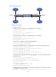
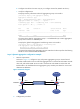
As shown in
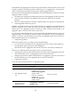
601HFigure 73, configure a Layer 2 dynamic aggregation group on Firewall A and
Firewall B. Enable VLAN 10 at one end of the aggregate link to communicate with VLAN 10 at the
other end, and enable VLAN 20 at one end to communicate with VLAN 20 at the other end.
Enable traffic to be load-shared across aggregation group member ports based on source and
destination IP addresses.
Figure 73 Network diagram
2. Configuration procedure
GE0/1
GE0/2
Link aggregation 1
GE0/1
GE0/2
BAGG1 BAGG1
Firewall A Firewall B
VLAN 10
VLAN 20
GE0/3
GE0/4
VLAN 10
VLAN 20
GE0/3
GE0/4