
F3726, F3211, F3174, R5135, R3816-HP Firewalls and UTM Devices High Availability Configuration Guide-6PW100

165
BAGG1 D 0x8000, 000f-e2ff-0002 2 0 Shar
The output shows that link aggregation group 1 is a load-shared Layer 2 dynamic aggregation
group, and it contains two Selected ports.
# Display the global link-aggregation load-sharing criteria on Firewall A.
[FirewallA] display link-aggregation load-sharing mode
Link-Aggregation Load-Sharing Mode:
destination-ip address, source-ip address
The output shows that all link aggregation groups created on the device perform load sharing
based on source and destination IP addresses.
367BLayer 2 aggregation load sharing configuration example
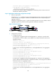
1. Network requirements
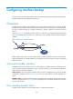
As shown in
602HFigure 74, configure two Layer 2 static aggregation groups (1 and 2) on Firewall A
and Firewall B, and enable VLAN 10 at one end of the aggregate link to communicate with VLAN
10 at the other end, and enable VLAN 20 at one end to communicate with VLAN 20 at the other
end.
Configure the load sharing criterion for link aggregation group 1 as the source IP addresses of
packets and the load sharing criterion for link aggregation group 2 as the destination IP addresses
of packets to enable traffic to be load-shared across aggregation group member ports.
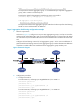
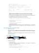
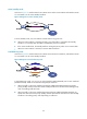
Figure 74 Network diagram
2. Configuration procedure
a. Configure Firewall A:
# Create VLAN 10, and assign port GigabitEthernet 0/5 to VLAN 10.
<FirewallA> system-view
[FirewallA] vlan 10
[FirewallA-vlan10] port gigabitethernet 0/5
[FirewallA-vlan10] quit
# Create VLAN 20, and assign port GigabitEthernet 1/1 to VLAN 20.
<FirewallA> system-view
[FirewallA] vlan 20
[FirewallA-vlan20] port gigabitethernet 1/1
[FirewallA-vlan20] quit