
F3726, F3211, F3174, R5135, R3816-HP Firewalls and UTM Devices High Availability Configuration Guide-6PW100


172
9BConfiguring interface backup
The term "router" in this document refers to both routers and routing-capable firewalls and UTM devices.
Interface backup can be configured only at the CLI.
52B
Overview
Interface backup increases network reliability. The active interface transmits services, and the standby
interfaces are in the backup state. When the active interface fails or the link fails, or when the traffic on
the active interface exceeds the configured threshold, a standby interface is activated to transmit
services.
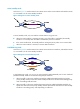
As shown in
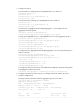
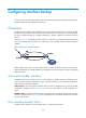
606HFigure 78, interfaces Serial 2/0, Serial 2/1, and Serial 2/2 on Router A back up each other.
Serial 2/0 transmits data, and Serial 2/1 and Serial 2/2 are standby interfaces that have different
priorities.
Figure 78 Diagram for interface backup
When interface Serial 2/0 or its link to Router B fails, or when the traffic on Serial 2/0 exceeds the
configured threshold, the standby interface with the highest priority is activated, ensuring uninterrupted
data transmission.
183BActive and standby interfaces
In interface backup, an interface can be an active interface or standby interface. Interfaces that can
serve as active or standby interfaces are: Layer 3 Ethernet interfaces, Layer 3 Ethernet subinterfaces,
dialer interfaces, and Tunnel interfaces.
Active interface—An active interface transmits data, and can be configured with up to three standby
interfaces (for example, Serial 2/0 in
607HFigure 78). Up to 10 active interfaces can be configured on a
device.
Standby interface—Standby interfaces function as backups for active interfaces (for example, interfaces
Serial 2/1 and Serial 2/2 in
608HFigure 78), which are generally idle. One standby interface can only back
up one active interface.
184BHow interface backup works
Interface backup operates in active/standby mode or in load balancing mode.