
F3726, F3211, F3174, R5135, R3816-HP Firewalls and UTM Devices High Availability Configuration Guide-6PW100

186
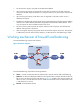
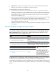
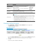
Figure 89 Network diagram
Cluster A adopts firewall load balancing, and Cluster B adopts NAT-mode server load balancing. This
networking mode not only prevents firewalls from becoming the bottleneck in the network, but also
enhances the performance and availability of multiple network services such as HTTP and FTP.
61B
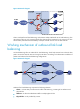
Working mechanism of outbound link load
balancing
Link load balancing refers to outbound link load balancing, which helps internal users select the best
path to access the external resources through an LB device according to the destination IP address of
packets and outbound link load balancing configurations.
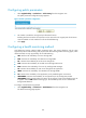
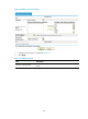
Figure 90 Network diagram
Outbound link load balancing comprises the following elements:
• Cluster—A cluster that provides network traffic load balancing, consisting of an LB device and
physical links
• LB device—A device that distributes traffic to multiple physical links.
• Physical links—Links provided by carriers.
ISP1
ISP2
ISP3
IP network
Router A
Router B
Router C
LB device
VSIP
Source Destination
Cluster