
F3726, F3211, F3174, R5135, R3816-HP Firewalls and UTM Devices High Availability Configuration Guide-6PW100

187
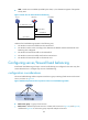
• VSIP—Virtual service IP address provided by the cluster, or, the destination segment of the packets
sent by users.
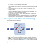
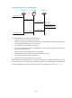
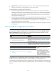
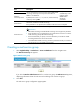
Figure 91 Work flow of outbound link load balancing
Outbound link load balancing operates in the following way:
1. The LB device receives the traffic from the internal users.
2. The LB device selects a link according to the destination IP address and the outbound link load
balancing rules configured.
3. The LB device forwards the traffic to the selected link.
4. The LB device receives the traffic sent from the external users.
5. The LB device forwards the traffic to the internal users.
62B
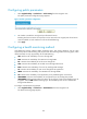
Configuring server/firewall load balancing
IPv4 firewall load balancing and Layer 4 server load balancing are configured in the same way. This
section describes how to configure Layer 4 server load balancing.
191Bconfiguration considerations
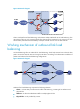
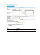
The server load balancing module comprises a real service group consisting of real services and a virtual
service, as shown in
619HFigure 92.
Figure 92 Relationship between the components of the server load balancing module
• Real service group—A group of real services.
• Real services—Entities that process services in a cluster (such as servers in
620HFigure 83, and 621HFigure 85,
and firewalls
622HFigure 87. A real service group comprises multiple real services.
LB device
(1) Traffic from source
Source Destination
(3) Distribute
(4) Traffic from destination
(5) Forward
(2) Scheduler