
F3726, F3211, F3174, R5135, R3816-HP Firewalls and UTM Devices High Availability Configuration Guide-6PW100


223
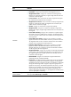
Statistics of all the virtual services of link load balancing are displayed on the page, including total
number of connections, average of active connections/peak of active connections, connection
average rate/peak rate, number of forwarded/ignored packets in the inbound direction, and
number of forwarded packets in the outbound direction.
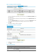
3. Click the link of a virtual service name.
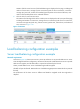
The statistics of all the logical links of the virtual service are displayed on the lower part of the page,
including total number of connections, average of active connections/peak of active connections,
connection average rate/peak rate, packets received, packets sent, inbound rate, and outbound
rate, as shown in
656HFigure 123.
Figure 123 Statistics
64B
Load balancing configuration examples
212BServer load balancing configuration example
383BNetwork requirements
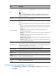
As shown in 657HFigure 124, three servers Server A, Server B, and Server C can provide HTTP services. Server
A has the highest hardware configuration, and Server B the second. Enable these three servers to provide
HTTP services together, and all HTTP traffic is required to be filtered by the firewall.
Cluster provides HTTP service. Server load balancing should be applied.
All traffic will pass the firewall: NAT-mode server load balancing (Responses in DR mode do not pass the
firewall).
The performance of the three servers is different and therefore weighted round robin algorithm is
adopted.