
F3726, F3211, F3174, R5135, R3816-HP Firewalls and UTM Devices High Availability Configuration Guide-6PW100

61
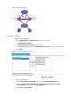
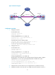
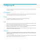
Figure 34 Network diagram
283BConfiguration procedure
1. Configure Firewall A:
# Create VLAN 100.
<FirewallA> system-view
[FirewallA] vlan 100
# Assign GigabitEthernet 0/1 to VLAN 100.
[FirewallA-vlan100] port gigabitethernet 0/1
[FirewallA-vlan100] quit
# Specify VLAN 100 as a backup VLAN.
[FirewallA] dhbk interface gigabitethernet 0/1 vlan 100
# Enable symmetric-path mode stateful failover.
[FirewallA] dhbk enable backup-type symmetric-path
2. Configure Device A:
# Create VLAN 100.
<DeviceA> system-view
[DeviceA] vlan 100
# Assign GigabitEthernet 1/1 to VLAN 100.
[DeviceA-vlan100] port gigabitethernet 1/1
[DeviceA-vlan100] quit
# Assign GigabitEthernet 1/2 to VLAN 100.
Because Device A and Device B may exchange packets of multiple VLANs, configure
GigabitEthernet 1/2 as a trunk port and permit packets of VLAN 100 to pass.
[DeviceA] interface gigabitethernet 1/2
[DeviceA-GigabitEthernet1/2] port link-type trunk
[DeviceA-GigabitEthernet1/2] port trunk permit vlan 100
Please wait... Done.
3. Configure Device B in the same way you configure Device A. (Details not shown.)
4. Configure Firewall B in the same way you configure Firewall A. (Details not shown.)
Internet
Internat
network
Device A Device B
GE1/2 GE1/2GE1/1 GE1/1
VLAN 100
GE1/2
Firewall A Firewall B
GE0/1 GE0/1
Failover Link Failover Link
VLAN 100VLAN 100