HP Firewalls and UTM Devices NAT and ALG Configuration Guide Part number: 5998-4166 Software version: F1000-A-EI: Feature 3722 F1000-S-EI: Feature 3722 F5000: Feature 3211 F1000-E: Feature 3174 Firewall module: Feature 3174 Enhanced firewall module: ESS 3807 U200-A: ESS 5132 U200-S: ESS 5132 Document version: 6PW100-20121228
Legal and notice information © Copyright 2012 Hewlett-Packard Development Company, L.P. No part of this documentation may be reproduced or transmitted in any form or by any means without prior written consent of Hewlett-Packard Development Company, L.P. The information contained herein is subject to change without notice.
Contents Configuring NAT ·························································································································································· 1 Overview············································································································································································ 1 NAT control ·······································································································································
Configuring a dynamic mapping policy on the IPv6 side ················································································ 39 Configuring IPv4/IPv6 address mappings on the IPv4 side ······················································································ 40 Configuring a static mapping on the IPv4 side ·································································································· 40 Configuring a dynamic mapping policy on the IPv4 side ··························
Index ··········································································································································································· 72 iii
Configuring NAT 1B Overview 6B Network Address Translation (NAT) provides a way to translate an IP address in the IP packet header to another IP address. NAT enables a large number of private users to access the Internet by using a small number of public IP addresses. NAT effectively alleviates the depletion of IP addresses. A private IP address is used only in an internal network, whereas a public or external IP address is used on the Internet and is globally unique.
The NAT operation is transparent to the terminals involved. The external server believes that the IP address of the internal PC is 20.1.1.1 and is unaware of the private address 192.168.1.3. As such, NAT hides the private network from the external networks. Despite the advantages of allowing internal hosts to access external resources and providing privacy, NAT also has the following disadvantages: • Because NAT involves translation of IP addresses, the IP headers cannot be encrypted.
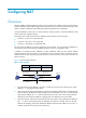
NAPT mapping is based on both the IP address and the port number. With NAPT, packets from multiple internal hosts are mapped to the same external IP address with different port numbers. Figure 2 NAPT operation Host A Direction Before NAT After NAT Outbound 192.168.1.2:1111 20.1.1.1:1001 Outbound 192.168.1.2:2222 20.1.1.1:1002 Outbound 192.168.1.3:1111 20.1.1.1:1003 Packet 1 Src : 192.168.1.2:1111 Packet 1 Src : 20.1.1.1:1001 Packet 2 Src : 192.168.1.2:2222 192.168.1.2 192.168.1.
You can configure an internal server on the NAT device by mapping a public IP address and port number to the private IP address and port number of the internal server. For instance, you can configure an address like 20.1.1.12:8080 as an internal Web server's external address and port number.
Easy IP 106B Easy IP uses the public IP address of an interface on the device as the translated source address to save IP address resources, and uses ACLs to permit only certain internal IP addresses to be NATed. NAT support for VPNs 107B NAT allows users from different VPNs to access external networks through the same outbound interface, and allows the VPN users to use the same private address space. 1.
An address pool is a set of consecutive public IP addresses used for dynamic NAT. A NAT gateway selects addresses from the address pool and uses them as the translated source IP addresses. To implement NAT for stateful failover (asymmetric-path), you must configure the same address pool on both devices so that one device can take over when the other device fails.
Configuring an internal server 12B Task Remarks Required. Configuring an internal server 23H After you map the private IP address/port number of an internal server to a public IP address/port number, hosts in external networks can access the server located in the private network. Optional.
Figure 6 Adding NAT Address Pool page 3. Create an IP address pool as described in Table 1. 4. Click Apply. 235H Table 1 Configuration items Item Description Index Specify the index of an address pool. Start IP Address Specify the start IP address of the address pool. End IP Address Specify the end IP address of the address pool. The end IP address must be identical to or higher than the start IP address. Configure the address pool as a low-priority or a non low-priority address pool.
Figure 7 Adding Dynamic NAT page 3. Configure dynamic NAT on an interface as described in Table 2. 4. Click Apply. 237H Table 2 Configuration items Item Description Interface Specify an interface on which dynamic NAT is to be enabled. Specify an ACL for dynamic NAT. You cannot associate an ACL with multiple NAT address pools, or associate an ACL with both Easy IP and an address pool.
Item Description Enable track to VRRP Configure whether to associate dynamic NAT on an interface with a VRRP group, and specify the VRRP group to be associated if you associate dynamic NAT on an interface with a VRRP group. When two network devices implement both stateful failover and dynamic NAT, • Make sure each address pool on an interface is associated with one VRRP group VRRP Group only. Otherwise, the system associates the address pool with the VRRP group having the highest group ID.
Figure 9 Adding Static Address Mapping page 3. Configure a static address mapping as described in Table 3. 4. Click Apply. 238H Table 3 Configuration item Item Description Specify a name of the VPN instance to which the internal IP addresses belong. Internal VPN Instance If no internal VPN instance is specified, this indicates that the internal address is a common private network address. Internal IP Address Enter an internal IP address for the static address mapping.
Figure 10 Enabling Interface Static Translation page 3. Enable static NAT on an interface as described in Table 4. 4. Click Apply. 239H Table 4 Configuration items Item Description Interface Name Select an interface to which static NAT is applied. Enable track to VRRP Configure whether to associate static NAT on an interface with a VRRP group, and specify the VRRP group to be associated if you associate static NAT on an interface with a VRRP group.
Figure 11 Internal server configuration page 2. In the Internal Server area, click Add. The Add Internal Server page appears.
Figure 12 Adding Internal Server page 3. Configure the internal server as described in Table 5. 4. Click Apply. 240H Configure advanced internal server settings 14B 1. Click Advanced in the page shown in Figure 13. 241H The Advanced Configuration page appears.
Figure 13 Configuring advanced internal server settings 2. Configure the internal server as described in Table 5. 3. Click Apply. 24H Table 5 Configuration items Item Description Interface Specify an interface to which the internal server policy is applied. Select the protocol to be carried by IP (Only supported by advanced configuration).
Item Description Specify the global port numbers for the internal server. This option is available when 6(TCP) or 17(UDP) is selected as the protocol type. You can: • For common configuration—Use the single box to specify a global port. 0 represents Global Port the default port of the specified service type. If the selected service type is any(TCP) or any(UDP), the global port is any port.
Item Description Enable track to VRRP Configure whether to associate the internal server on an interface with a VRRP group, and specify the VRRP group to be associated if you associate the internal server on an interface with a VRRP group. When two network devices deliver both stateful failover and dynamic NAT, • Make sure each address pool on an interface is associated with one VRRP group VRRP Group only.
Item Description Enter the port number of the internal server. This option is available when 6(TCP) or 17(UDP) is selected for the protocol type. If you enter 0 in the field, all types of services are provided which indicates a static connection exists between the internal address and external address. Internal Port Configuring DNS mapping 52B 1. From the navigation tree, select Firewall > NAT Policy > Internal Server. 2. In the DNS-MAP area, click Add. The page for adding DNS-MAP appears.
Figure 16 Network diagram Configuring Firewall 16B 1. Configure an ACL to permit internal users in subnet 10.110.10.0/24 to access the Internet: a. From the navigation tree, select Firewall > ACL. b. Click Add. c. Enter 2001 in ACL Number, and click Apply. Figure 17 Defining ACL 2001 d. Click the icon in the operation column corresponding to ACL 2001 to enter the ACL 2001 configuration page. e. Click Add. f. On the page that appears, select Permit in Operation.
Figure 18 Configuring ACL 2001 to permit users on network 10.110.10.0/24 to access the Internet h. Click Add on the ACL 2001. Select Deny for Operation, and click Apply. Figure 19 Configuring ACL 2001 to prohibit other users to access the Internet 2. Configure a NAT address pool: a. From the navigation tree, select Firewall > NAT Policy > Dynamic NAT. b. Click Add. c. On the page that appears as shown in Figure 20, enter 0 in Index, enter 202.38.1.2 in Start IP Address and enter 202.38.1.
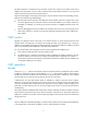
e. Click Apply. Figure 21 Configuring dynamic NAT Internal server configuration example 54B Network requirements 17B As illustrated in Figure 22, a company provides two Web servers and one FTP server for external users to access. The internal network address is 10.110.0.0/16. The internal address for the FTP server is 10.110.10.3/16, for the Web server 1 is 10.110.10.1/16, and for the Web server 2 is 10.110.10.2/16. The company has three public IP addresses from 202.38.1.1/24 through 202.38.1.3/24.
e. Select the first option for Global Port and enter 21. f. Enter 10.110.10.3 in the Internal IP field. g. Select the service type ftp. h. Click Apply. Figure 23 Configuring an internal FTP server 2. Configure the Web server 1: a. Click Add in the Internal Server area. b. On the page that appears, select GigabitEthernet0/1 for Interface. c. Select the Assign IP Address option, and enter 202.38.1.1. d. Select the first option for Global Port and enter 80. e. Enter 10.110.10.1 in the Internal IP field.
Figure 24 Configuring internal Web server 1 3. Configure the Web server 2: a. Click Add in the Internal Server area. b. On the page that appears, select GigabitEthernet0/1 for Interface. Select the Assign IP Address option, and enter 202.38.1.1. Select the first option for Global Port and enter 8080. Enter 10.110.10.2 in the Internal IP field. Select the service type www. c. Click Apply.
Figure 25 Configuring internal Web server 2 Configuring NAT at the CLI 9B NAT configuration task list 5B Task Remarks Configure address translation: • Configuring static NAT • Configuring dynamic NAT Either is required. Configuring an internal server Required. Configuring DNS mapping Optional.
Configuring static NAT 56B Static NAT supports NAT multiple-instance as long as the VPN instance of an IP address is provided. Static NAT supports two modes: one-to-one and net-to-net. Configuring one-to-one static NAT 19B One-to-one static NAT translates a private IP address into a public IP address. To configure one-to-one static NAT: Step Command 1. Enter system view. system-view 2. Configure a one-to-one static NAT mapping.
Configuring NAT address pools 12B You can configure NAT address pools in two ways: • Configure an address pool that consists of a set of consecutive addresses. • Configure an address group that can contain several members. Each member specifies an address pool that consists of a set of consecutive addresses. The address pools of members may not be consecutive. The NAT device selects an IP address from a specific NAT address pool as the source address of a packet.
Step Command 1. Enter system view. system-view 2. Enter interface view. interface interface-type interface-number 3. Configure No-PAT by associating an ACL with an IP address pool on the outbound interface for translating only IP addresses.
Step Command Remarks • nat server [ index | acl-number ] protocol pro-type global 3. Configure a common internal server.
Step Command 1. Enter system view. system-view 2. Enter interface view. interface interface-type interface-number 3. Configure an internal server based on ACL. nat server protocol pro-type global acl-number inside local-address [ local-port ] [ vpn-instance local-name ] Configuring DNS mapping 60B With DNS mapping, an internal host can access an internal server on the same private network by using the domain name of the internal server when the DNS server resides on the public network.
Figure 26 Network diagram Configuration procedure 128B # As shown in Figure 26, configure the IP addresses for the interfaces. (Details not shown.) 253H # Configure a one-to-one static NAT mapping. system-view [Firewall] nat static 10.110.10.8 202.38.1.100 # Enable static NAT on interface GigabitEthernet 0/2.
# Associate address pool 1 and ACL 2001 with the outbound interface GigabitEthernet 0/2.
[Firewall-GigabitEthernet0/2] nat server protocol tcp global 202.38.1.1 8080 inside 10.110.10.2 www # Configure the internal SMTP server. [Firewall-GigabitEthernet0/2] nat server protocol tcp global 202.38.1.1 smtp inside 10.110.10.4 smtp [Firewall-GigabitEthernet0/2] quit NAT DNS mapping configuration example 65B Network requirements 13B As shown in Figure 29, a company provides Web and FTP services to external users, and uses internal IP network segment 10.110.0.0/16.
[Firewall] quit Verifying the configuration 135B # After completing the configurations, display the DNS mapping configuration information. display nat dns-map NAT DNS mapping information: There are currently 2 NAT DNS mapping(s) Domain-name: www.server.com Global-IP : 202.38.1.2 Global-port: 80(www) Protocol : 6(TCP) Domain-name: ftp.server.com Global-IP : 202.38.1.2 Global-port: 21(ftp) Protocol : 6(TCP) Host A and Host B can use the domain name www.server.
Configuring NAT-PT 2B NAT-PT can be configured only at the CLI. NAT-PT is not supported on VLAN interfaces and does not support VPN instances, IPv4 fragments, or ICMPv6 fragments.
Basic concepts 70B NAT-PT mechanism 136B There are three NAT-PT mechanisms to realize translation between IPv4 and IPv6 addresses: static mapping, dynamic mapping, and NAPT-PT: Static mapping • Static mappings are manually configured for translation between IPv6 and IPv4 addresses. • Dynamic mapping Dynamic mappings are dynamically generated for translation between IPv6 and IPv4 addresses.
2. Translates the source IP address. The NAT-PT device translates the source IPv6 address of the packet into an IPv4 address according to the static or dynamic mapping on the IPv6 side. 3. Translates the destination IP address. The NAT-PT device translates the destination IPv6 address of the packet into an IPv4 address according to the static mapping, if configured, on the IPv4 network side.
NAT-PT limitations 72B Because of the following limitations, NAT-PT is not recommended in some applications. For example, tunneling is recommended in the case where an IPv6 host needs to communicate with another IPv6 host across an IPv4 network. • In NAT-PT translation, the request and response packets of a session must be processed by the same NAT-PT device. • The Options field in the IPv4 packet header cannot be translated. • NAT-PT does not provide end-to-end security.
Task Remarks Configuring IPv4/IPv6 address mappings on the IPv4 side Required. 270H Configuring static NAPT-PT mappings of IPv6 servers Complete either task. Setting the traffic class field after NAT-PT translation Optional. 269H 271H Configuration prerequisites 14B Before you implement NAT-PT, complete the following tasks: 1. Enable IPv6 on the device. For more information, see Network Management Configuration Guide. 2.
Configuring IPv4/IPv6 address mappings on the IPv6 side 17B IPv4/IPv6 address mappings on the IPv6 side can be static or dynamic. Configuring a static mapping on the IPv6 side 74B A static mapping on the IPv6 side shows the one-to-one correspondence between an IPv4 address and an IPv6 address: • If the source IPv6 address in a packet sent from an IPv6 host to an IPv4 host matches the static mapping, the source IPv6 address is translated into the corresponding IPv4 address.
if policy 1 or 3 is set, the NAT-PT device will select an IPv4 address from the NAT-PT address pool as the source IPv4 address of the IPv6 packet. To configure a dynamic IPv4/IPv6 address mapping policy on the IPv6 side: Step Command Remarks 1. Enter system view. system-view N/A 2. Configure a NAT-PT address pool. natpt address-group group-number start-ipv4-address end-ipv4-address Skip this step if you use policy 2 or policy 4.
Step Command 1. Enter system view. system-view 2. Configure a static IPv4/IPv6 address mapping on the IPv4 side. natpt v4bound static ipv4-address ipv6-address Configuring a dynamic mapping policy on the IPv4 side 7B A dynamic IPv4/IPv6 address mapping policy on the IPv4 side is that if the source IPv4 address matches a specific ACL, the source IPv4 address is added with a NAT-PT prefix as the translated IPv6 address.
Step Set the Traffic Class field in IPv6 packets translated from IPv4 packets to 0. 2. Command Remarks natpt turn-off traffic-class By default, the value of the Traffic Class field of IPv6 packets is the same as that of the ToS field in corresponding IPv4 packets. Configuring static NAPT-PT mappings of IPv6 servers 21B Generally, a server such as the FTP server, Web server, or Telnet server on an IPv6 network provides services for IPv6 hosts only.
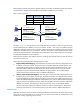
Task Command Remarks Clear all NAT-PT statistics information. reset natpt statistics Available in user view. NAT-PT configuration examples 23B Configuring dynamic mapping on the IPv6 side 78B Network requirements 140B As shown in Figure 32, Router B with IPv6 address 2001::2/64 on an IPv6 network wants to access Router A with IPv4 address 8.0.0.2/24 on an IPv4 network, whereas Router A cannot actively access Router B.
system-view [RouterA] interface gigabitethernet 0/1 [RouterA-GigabitEthernet0/1] ip address 8.0.0.2 255.255.255.0 [RouterA-GigabitEthernet0/1] quit # Configure a static route to subnet 9.0.0.0/24. [RouterA] ip route-static 9.0.0.0 24 8.0.0.1 3. Configure Router B on the IPv6 side: # Enable IPv6. system-view [RouterB] ipv6 # Configure an IP address for GigabitEthernet 0/1.
# Configure a NAT-PT prefix. [Firewall] natpt prefix 3001:: # Configure a static IPv4/IPv6 mapping on the IPv4 side. [Firewall] natpt v4bound static 9.0.0.2 3001::5 # Configure a static IPv4/IPv6 mapping on the IPv6 side. [Firewall] natpt v6bound static 2001::2 8.0.0.5 2. Configure Router A: # Configure an IP address for GigabitEthernet 0/1. system-view [RouterA] interface gigabitethernet 0/1 [RouterA-GigabitEthernet0/1] ip address 8.0.0.2 255.255.255.
NAT444 3B The device does not support stateful failover of the NAT444 feature. NAT444 can be configured only at the CLI. Feature and hardware compatibility 25B Hardware NAT444 compatible F1000-A-EI/F1000-S-EI No F1000-E No F5000 No Firewall module Yes U200-A No U200-S No Overview 26B NAT444 translates an IPv4 address to another IPv4 address to a third IPv4 address.
Static mappings 83B Figure 35 User tracing process Transition technology deployment scheme contains two IP-port mapping modes: static and dynamic. • Static IP-port mapping mode—AAA and Carrier Grade NAT (CGN) set parameters through the network management system and execute the same algorithm for generating mappings. During address tracing process, AAA and CGN do not exchange mappings with each other, and trace the address directly.
Figure 36 NAT unlimited connection User connection limit 85B You can use connection limit to prevent large amount of resources being occupied because of excessive sessions and to prevent external attacks after FullCone NAT is enabled. Full cone NAT 86B Enable Full cone NAT when the P2P node is behind a NAT device and provides external download services. Multiple routing protocols 87B NAT444 supports static routes and policy-based routes as well as dynamic routes such as OSPF, BGP, and ISIS.
Step Command Remarks Enter system view. system-view N/A 2. Configure a NAT444 static IP-port mapping. nat444 static local local-start-address local-end-address [ vpn-instance local-name ] global global-start-address global-end-address port-range port-range-start port-range-end block-size block-size The command takes effect globally. 3. Enter interface view. interface interface-type interface-number N/A 4. Enable static NAT444 on the interface to make the static IP-port mapping take effect.
Configuration procedure 89B Step Command Remarks 1. Enter system view. system-view N/A 2. Enter interface view. interface interface-type interface-number N/A Configure an outbound NAT444. 3. nat444 outbound acl-number address-group group-number port-range port-range-start port-range-end block-size block-size The ACL can be modified and also can be nonexistent. The configuration does not take effect when the ACL does not exist.
Configuring NAT444 logging 32B NAT444 sends the following logs to the log server when an internal user access the Internet through NAT444: • NAT444 user log • NAT444 session establishment log • NAT444 session removal log NAT444 logs support two formats: china-telecom and china-unicom-nat444. You can configure the two formats by executing the info-center format command.
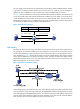
Figure 37 A BRAS with 1 to n NAT444 gateways network diagram IPv4 network IPv6 network CR-1 IPv4 network CR-2 IPv6 network CR-1 MAN CR-2 MAN NAT444 NAT444-1 BRAS SR BRAS BRAS SR BRAS NAT444-2 Routing users Bridging users Bridging users a) Distributed bypass NAT444 • Routing users b) Distributed inserted card NAT444 Bypass core router Figure 38 A CR with 1 to n NAT444 gateways network diagram IPv4 network NAT444-1 IPv6 network NAT444-3 IPv4 network IPv6 network CR-1 CR-1 CR-2
Configuration procedure 91B This configuration example is only for the NAT444 device. For configurations about other network devices, see the descriptions about the related features. • Configure a static NAT444 IP-port mapping: # Configure a static NAT444 IP-port mapping. system-view [Sysname] nat444 static local 192.168.1.1 192.168.1.100 global 201.1.1.1 201.1.1.10 port-range 10001 20000 block-size 1000 # Enable static NAT444 on the outbound interface to make the IP-port mapping take effect.
• 192.168.1.95 <-> 201.1.1.10 : (14001 - 15000 ) 192.168.1.96 <-> 201.1.1.10 : (15001 - 16000 ) 192.168.1.97 <-> 201.1.1.10 : (16001 - 17000 ) 192.168.1.98 <-> 201.1.1.10 : (17001 - 18000 ) 192.168.1.99 <-> 201.1.1.10 : (18001 - 19000 ) 192.168.1.100 <-> 201.1.1.10 : (19001 - 20000 ) Configure a dynamic NAT444 IP-port mapping: # Configure address pool 1. System-view [Sysname] nat address-group 1 201.1.1.1 201.1.1.10 # Create ACL 3000, permitting packets from 192.168.1.
Configuring ALG 4B Application Level Gateway (ALG) processes the payload information of application layer packets to make sure data connections can be established. Usually NAT translates only IP address and port information in packet headers and does not analyze fields in application layer payloads. However, the packet payloads of some protocols may contain IP address or port information, which may cause problems if not translated.
ALG process 35B The following example describes the FTP operation of an ALG-enabled device. As shown in Figure 39, the host on the external network accesses the FTP server on the internal network in passive mode through the ALG-enabled device. 280H Figure 39 Network diagram for ALG-enabled FTP application in passive mode The communication process includes the following steps: 1. Establishing a control connection. The host sends a TCP connection request to the server.
4. Exchanging data. The host and the FTP server exchange data through the established data connection. Configuring ALG in the Web interface 36B By default, ALG is enabled only for FTP. Configuration procedure 92B To enable ALG for protocols: 1. From the navigation tree, select Firewall > ALG. Figure 40 ALG configuration page 2. Add target application protocols to the Selected Application Protocols list to enable ALG for them. By default, ALG is enabled for all protocols. 3. Click Apply.
Figure 41 Network diagram Internet 192.168.1.1/24 FTP server Firewall GE0/1 5.5.5.1/24 Host Local: 192.168.1.2 Global: 5.5.5.10 Configuration procedure 145B This section describes ALG configuration only, assuming that other required configurations on the server and client have been done. 1. Enable ALG for FTP. (By default, ALG is enabled for FTP, and this step can be skipped.) a. Select Firewall > ALG from the navigation tree. b. Add ftp to the Selected Application Protocols list. c. Click Apply.
Figure 43 Adding an internal FTP server SIP/H.323 ALG configuration example 94B H.323 ALG configuration is similar to SIP ALG configuration. This example discusses SIP ALG configuration. Network requirements 146B As shown in Figure 57, a company uses the private network segment 192.168.1.0/24, and has four public network addresses: 5.5.5.1, 5.5.5.9, 5.5.5.10, and 5.5.5.11. SIP UA 1 is on the internal network and SIP UA 2 is on the outside network.
a. Select Firewall > ALG from the navigation tree. b. Add sip to the Selected Application Protocols list. c. Click Apply. Figure 45 Enabling ALG for SIP 2. Configure ACL 2001: a. Select Firewall > ACL from the navigation tree. b. Click Add. c. Enter 2001 in the ACL Number field. d. Select Config as the match order. e. Click Apply. Figure 46 Adding ACL 2001 f. Click the icon for ACL 2001. g. Click Add. h. Select Permit as the operation.
i. Select Source IP Address, enter 192.168.1.0 as the source IP address, and enter 0.0.0.255 as the source wildcard. j. Click Apply. Figure 47 Configuring an ACL rule to permit packets sourced from 192.168.1.0/24 k. Click Add. l. Select Deny as the operation. m. Click Apply. Figure 48 Configuring an ACL rule to deny packets 3. Configure the NAT address pool: a. Select Firewall > NAT Policy > Dynamic NAT from the navigation tree. b. In the Address Pool area, click Add. c.
Figure 49 Adding a NAT address pool 4. Configure dynamic NAT: a. In the Dynamic NAT area, click Add. b. Select GigabitEthernet0/1. c. Enter 2001 for the ACL field. d. Select PAT as the address translation. e. Enter 1 as the address pool index. f. Click Apply. Figure 50 Configuring dynamic NAT NBT ALG configuration example 95B Network requirements 148B As shown in Figure 58, a company using the private network segment 192.168.1.0/24 wants to provide NBT services to the outside.
Figure 51 Network diagram Configuration procedure 149B This section describes ALG configuration only, assuming that other required configurations on the server and client have been done. 1. Enable ALG for NBT: a. Select Firewall > ALG from the navigation tree. b. Add nbt to the Selected Application Protocols list. c. Click Apply. Figure 52 Enabling ALG for NBT 2. Configure static NAT: a. Select Firewall > NAT > Static NAT from the navigation tree. b. In the Static Address Mapping area, click Add. c.
Figure 53 Adding a static address mapping 3. Configure static NAT for interface GigabitEthernet 0/1: a. In the Interface Static Translation area, click Add. b. Select GigabitEthernet0/1. c. Click Apply. Figure 54 Configuring static NAT for interface GigabitEthernet 0/1 4. Configure an internal WINS server: a. Select Firewall > NAT > Internal Server from the navigation tree. b. In the Internal Server area, click Add. c. Select GigabitEthernet0/1. d. Select 17(UDP) as the protocol type, e. Enter 5.5.
Figure 55 Configuring an internal WINS server j. In the Internal Server area, click Add. Configure an interval WINS server, which is similar to the configuration shown in Figure 55. 284H k. Select GigabitEthernet0/1. l. Select 17(UDP) as the protocol type, m. Enter 5.5.5.10 as the external IP address. n. Enter 138 as the global port. o. Enter 192.168.1.2 as the internal IP address. p. Enter 138 as the internal port. q. Click Apply. r. In the Internal Server area, click Add.
Configuring ALG at the CLI 37B Step Command Remarks 1. Enter system view. system-view N/A 2. Enable ALG. alg { all | dns | ftp | gtp | h323 | ils | msn | nbt | pptp | qq | rtsp | sccp | sip | sqlnet | tftp } Optional. By default, ALG is enabled only for FTP. FTP ALG configuration example 96B Network requirements 150B As shown in Figure 56, a company uses the private network segment 192.168.1.0/24. The company wants to provide FTP services using public IP address 5.5.5.10.
Figure 57 Network diagram Configuration procedure 153B This section describes ALG configuration only, assuming that other required configurations on the server and client have been done. # Configure the address pool and ACL. system-view [Firewall] nat address-group 1 5.5.5.9 5.5.5.11 [Firewall] acl number 2001 [Firewall-acl-basic-2001] rule permit source 192.168.1.0 0.0.0.255 [Firewall-acl-basic-2001] rule deny [Firewall-acl-basic-2001] quit # Enable ALG for SIP.
Configuration procedure 15B This section describes ALG configuration only, assuming that other required configurations on the server and client have been done. # Configure a static NAT entry. system-view [Firewall] nat static 192.168.1.3 5.5.5.9 # Enable ALG for NBT. [Firewall] alg nbt # Configure NAT. [Firewall] interface gigabitethernet 0/2 [Firewall-GigabitEthernet0/2] nat outbound static # Configure the internal WINS server. [Firewall-GigabitEthernet0/2] nat server protocol udp global 5.
Support and other resources 5B Contacting HP 38B For worldwide technical support information, see the HP support website: http://www.hp.
Conventions 40B This section describes the conventions used in this documentation set. Command conventions 156B Convention Description Boldface Bold text represents commands and keywords that you enter literally as shown. Italic Italic text represents arguments that you replace with actual values. [] Square brackets enclose syntax choices (keywords or arguments) that are optional. { x | y | ...
Network topology icons 159B Represents a generic network device, such as a router, switch, or firewall. Represents a routing-capable device, such as a router or Layer 3 switch. Represents a generic switch, such as a Layer 2 or Layer 3 switch, or a router that supports Layer 2 forwarding and other Layer 2 features. Represents a firewall product or a UTM device. Port numbering in examples 160B The port numbers in this document are for illustration only and might be unavailable on your device.
Index 0B ACDEFNORST 1H 12H 13H 14H 15H 16H 17H 18H 19H 120H Enabling NAT-PT,38 A 308H ALG process,56 F C Feature and hardware compatibility,34 289H 309H Feature and hardware compatibility,46 Configuration guidelines,6 310H Features,46 290H Configuration prerequisites,38 31H 291H Configuring a NAT-PT prefix,38 N Configuring ALG at the CLI,66 NAT444 configuration examples,51 29H 293H 312H Configuring ALG in the Web interface,57 NAT444 configuration task list,48 294H 31H