
F3726, F3211, F3174, R5135, R3816-HP Firewalls and UTM Devices Network Management Configuration Guide-6PW100


103
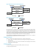
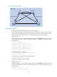
Figure 58 Network diagram
1161BConfiguration procedure
1. Configure VLANs and VLAN member ports: (Details not shown.)
Create VLAN 10, VLAN 20, and VLAN 30 on Device A and Device B, respectively. Create VLAN
10, VLAN 20, and VLAN 40 on Device C, and VLAN 20, VLAN 30, and VLAN 40 on Device D.
Configure the ports on these devices as trunk ports and assign them to related VLANs.
2. Configure Device A:
# Enter MST region view and configure the MST region name as example. Map VLAN 10, VLAN
30, and VLAN 40 to MSTI 1, MSTI 3, and MSTI 4, respectively. Configure the revision level of the
MST region as 0.
<DeviceA> system-view
[DeviceA] stp region-configuration
[DeviceA-mst-region] region-name example
[DeviceA-mst-region] instance 1 vlan 10
[DeviceA-mst-region] instance 3 vlan 30
[DeviceA-mst-region] instance 4 vlan 40
[DeviceA-mst-region] revision-level 0
# Activate MST region configuration.
[DeviceA-mst-region] active region-configuration
[DeviceA-mst-region] quit
# Specify the current device as the root bridge of MSTI 1.
[DeviceA] stp instance 1 root primary
# Enable the spanning tree feature globally.
[DeviceA] stp enable
3. Configure Device B:
# Enter MST region view, and configure the MST region name as example. Map VLAN 10, VLAN
30, and VLAN 40 to MSTI 1, MSTI 3, and MSTI 4, respectively. Configure the revision level of the
MST region as 0.
<DeviceB> system-view
[DeviceB] stp region-configuration
Permit: all VLAN
P
e
r
mi
t:
V
L
A
N
2
0
,
3
0
P
e
r
m
i
t
:
V
L
A
N
1
0
,
2
0
Permit: VLAN 20, 40
Permit: VLAN 20, 30Permit: VLAN 10, 20
Device A Device B
Device C Device D
GE0/3
G
E
0
/
2
GE0/3
G
E
0
/
2
GE0/3 GE0/3
G
E
0
/
2
G
E
0
/
2
MST region