
F3726, F3211, F3174, R5135, R3816-HP Firewalls and UTM Devices Network Management Configuration Guide-6PW100


106
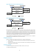
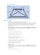
Figure 59 MSTIs mapped to different VLANs
82B
Configuration guidelines
Follow these guidelines when you configure MSTP:
• Two or more spanning tree-enabled devices belong to the same MST region only if the following are
true:
{ They are configured with the same format selector (0 by default, not configurable), MST region
name, VLAN-to-instance mapping entries in the MST region, and MST region revision level.
{ They are interconnected through physical links.
• If two or more devices have been designated to be root bridges of the same spanning tree instance,
MSTP selects the device with the lowest MAC address as the root bridge.
• The values of forward delay, hello time, and max age are interdependent. Inappropriate settings of
these values may cause network flapping.
HP recommends that you not manually set the spanning tree timers. Instead, you can specify the
network diameter and let spanning tree protocols automatically calculate the timers based on the
network diameter.
To prevent network instability, make sure the timer settings meet the following formulas:
{ 2 × (forward delay – 1 second) ≥ max age
{ Max age ≥ 2 × (hello time + 1 second)
• If the device is not enabled with BPDU guard, when a boundary port receives a BPDU from another
port, it transits into a non-boundary port. To restore its port role as a boundary port, you need to
restart the port.
A
B
A B
C D
C
B
C
MSTI 1 mapped to VLAN 10
A
D D
Root bridge Normal link Blocked link
MSTI 3 mapped to VLAN 30
MSTI 0 mapped to VLAN 20
MSTI 4 mapped to VLAN 40