
F3726, F3211, F3174, R5135, R3816-HP Firewalls and UTM Devices Network Management Configuration Guide-6PW100

163
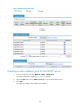
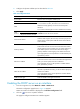
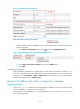
Figure 97 Configuring a DHCP server interface
3. Select the Enable option.
4. Click Apply.
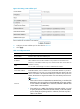
Table 23 Configuration items
Item Descri
p
tion
Interface Name This field displays the name of a specific interface.
DHCP Server
Enable or disable the DHCP server on the interface.
Upon receiving a DHCP request from a client, the interface with the DHCP server
disabled neither assigns an IP address to the client, nor serves as a DHCP relay agent
to forward the request.
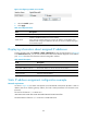
494BDisplaying information about assigned IP addresses
From the navigation tree, select Network > DHCP > DHCP Server to enter the page as shown in 2361HFigure 94.
In the Address In Use field, you can view the information about the IP address assigned from the address
pool.
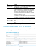
2362HTable 24 describes the information about the assigned IP address.
Table 24 Field description
Field Descri
p
tion
IP Address Assigned IP address.
Client MAC Address/Client ID Client MAC address or client ID bound to the IP address.
Pool Name Name of the DHCP address pool where the IP address resides.
Lease Expiration Lease time of the IP address.
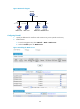
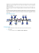
495BStatic IP address assignment configuration example
1199BNetwork requirements
As shown in 2363HFigure 98, the DHCP client (Router A) and the BOOTP client (Router B) obtain a static IP
address, DNS server address, gateway address, and other related parameters from the DHCP server
(Firewall).
The client ID of Ethernet 1/1 on Router A is:
3030-3066-2e65-3230-302e-3030-3032-2d45-7468-6572-6e65-7430-2f30.
The MAC address of Ethernet 1/1 on Router B is: 000f-e200-01c0.