
F3726, F3211, F3174, R5135, R3816-HP Firewalls and UTM Devices Network Management Configuration Guide-6PW100

166
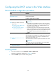
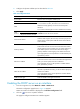
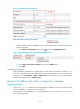
Figure 101 Creating a static address pool
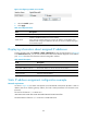
5. Enable the DHCP server on GigabitEthernet 0/1. With DHCP enabled, interfaces operate in the
DHCP server mode:
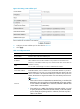
a. In the Interface Configuration field, click the icon next to GigabitEthernet 0/1.
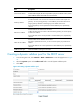
Figure 102 Enabling DHCP server on interface GigabitEthernet 0/1
b. On the DHCP Server Interface Config page, select the Enable option.
c. Click Apply.
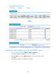
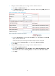
1201BVerifying the configuration
After the preceding configuration is complete, Router A and Router B can obtain IP addresses 10.1.1.5
and 10.1.1.6 respectively, and other configuration information from the DHCP server on Firewall. From the
navigation tree, select Network > DHCP > DHCP Server on Firewall and view the client IP address
assigned by the DHCP server in Address in Use.
496BDynamic IP address allocation configuration example
1202BNetwork requirements
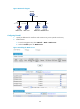
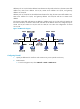
As shown in 2364HFigure 103, the DHCP server (Firewall) assigns IP address to clients on subnet 10.1.1.0/24,
w h i c h i s s u b n e t t e d i n t o 10 .1.1. 0 / 2 5 a n d 10 .1.1.12 8 / 2 5 .
The IP addresses of GigabitEthernet 0/1 and GigabitEthernet 0/2 on Firewall are 10.1.1.1/25 and
10 .1.1.12 9 / 25 r e s p e c t i v e l y.